E721 15 532014 - Rev.E
ENGLISH
7.3 POSITIONING LIMIT SWITCHES
To ensure correct positioning of the limit switch magnets, the control unit must be installed and
correctly connected with all control and safety accessories.
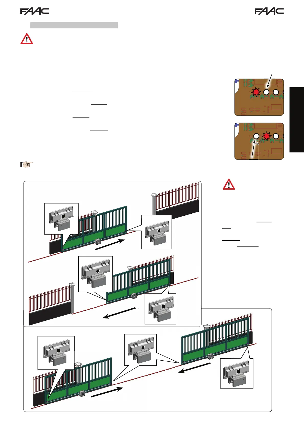
The operator is equipped with a magnetic limit switch sensor built directly into the electronic control board.
The gate is stopped, during opening or closing, when the polarised magnet secured to the upper part of the rack
activates the sensor.
1. Check that the operator is set for manual operating mode as described in the instructions
for the operator.
2. Move the gate to opening position manually, leaving 40 mm from the limit switch me-
chanical stop (see Fig. 17).
3. Slide the magnet with the CIRCLE on the rack in the direction of the motor. As soon as
the LED for the FCA limit switch on the board goes off, secure with the appropriate screws.
4. Move the gate to closing position manually, leaving 40 mm from the limit switch me-
chanical stop.
5. Slide the magnet with the SQUARE on the rack in the direction of the motor. As soon as
the LED for the FCC limit switch on the board goes off, secure with the appropriate screws.
6. Check that the relevant limit switch LED goes off correctly at the end of the opening and
closing movement and make the necessary changes to the position of the limit switch
magnet position if necessary.
To avoid damage to the operator and/or interruptions in the operation of the
automated system, approximately 40 mm must be left from the mechanical
limit switch stops.
For correct opera-
tion of the opera-
tor, the magnet with
the CIRCLE must be
used as an OPEN-
ING limit switch and
the magnet with the
SQUARE must be used
as a CLOSING limit
switch.
(SEE FIG. 17)
When using a system
with MASTER/SLAVE
configuration, the
limit switch magnets
must be installed as
shown in Fig. 18.
MASTER/SLAVE
Fig. 18
Fig. 17