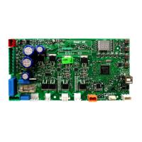
E721 17 532014 - Rev.E
ENGLISH
7.5 SETUP
When the board is powered when no SETUP
has ever been carried out, or if the board requires it,
the code
S0 will flash on the display together with the
SETUP LED to indicate that SETUP must be carried out.
To ensure the effective outcome of the SETUP
procedure, carefully check the correct polarity of the
magnetic limit switches as described in the previous
paragraph.
Proceed as follows to carry out the SETUP:
1. Place the gate at half its travel (very important for a
successful SETUP) and check that both the FCA and
FCC LEDs are on. Otherwise, the board will signal
error 12 (see tab. 5)
2. Press and hold the SETUP (SW4) push-button until the
gate begins to move slowly and stops when it reaches
the limit switch. If the limit switch reached is the closing
switch (with the SQUARE) the device stores that point
as the closing stop, conversely if the limit switch is the
opening switch (with the CIRCLE) the device stores
that point as the opening stop. During that stage,
S1
flashes on the display
3. The gate automatically begins to move slowly in the
opposite direction and then stops when it reaches the
limit switch. If the limit switch reached is the opening
switch (with the SQUARE) the device stores that point
as the opening stop, conversely if the limit switch is
the closing switch (with the SQUARE) the device stores
that point as the closing stop. During that stage,
S3 flashes on the display
4. According to the final limit switch reached, the device
takes up a status of closed (
00) or open (01). In the
second case, issue an OPEN pulse to close the gate.
8 TESTING THE AUTOMATED SYSTEM
After installation and programming, check the system is
operating correctly. Above all, check that the safety de-
vices operate correctly and ensure that the current safety
regulations are met.
Remember that the second programming level
features the encoder configuration parameter (para-
meter
EC
). This “virtual” encoder located on the board
acts as an anti-crushing device. During the open/clo-
sing phase, should the gate collide with an obstacle,
the “virtual” encoder will cause the motion to reverse.
At the next motion in the same direction, an obstacle
in the same position will cause the motor to stop. It
is essential to correctly configure this parameter to
adjust the correct sensitivity of the “virtual” encoder
with respect to obstacles during motion.
9 ALARM AND ERROR SIGNALS
If alarms occur (conditions that do not impair the opera-
tion of the gate) or errors (conditions that lock the gate
operation) the display shows a number relating to the
current condition.
The ALARM or ERROR signals disappear at the
next cycle only if the triggering cause is removed.
9.1 ALARMS
When an ALARM occurs, the ERROR LED begins
to flash and a number relating to the current fault ap-
pears on the display when the + and - keys are pressed.
Tab. 4 indicates all the alarms that may be shown on the
display.
Tab. 4 - Alarms
22
Limited MOTOR current
24
LAMP output short-circuited
27
Obstacle detection (visible for 10 secs)
30
XF radio code memory-module full (visible
for 10 secs)
40
Service request
46
Forced default programming reset
9.2 ERRORS
When an ERROR occurs, LED DL20 comes on
with a fixed light and a number relating to the current
fault appears on the display when the + and - keys are
pressed.
Tab. 5 indicates all the errors that may be shown on the
display.
Tab. 5 - Errors
01
Board faulty
03
Motor faulty
05
FailSafe error
06
Motor lock locked closed (check the motor
lock and replace if necessary)
07
Gate too heavy or too much friction (try to
increase motor power)
08
BUS-2EASY device error (e.g. same address
on two photocell pairs; check address)
09
Bus2Easy anomaly
10
Both limit switches with the same polarity
12
Limit switch engaged at the beginning of
SETUP
15
Time-out finished
90
No communication with the SLAVE unit -
SLAVE unit missing
91
Error on the SLAVE unit
92
Error on the SLAVE unit
97
Configuration error (C720 detected). Repeat
setup
98
Configuration error (C721 detected). Repeat
setup
99
Board faulty
Errors
90
91
and
92
are displayed only on
E721 configured as MASTER and in particular
91and
92
indicate errors present on the SLAVE unit. Should
such errors be displayed, we recommend you check on
the SLAVE unit the type of error shown on the display
to solve it and restore correct operation of the system.

 Loading...