Fig. 11 Fig. 13
Fig. 14
Fig. 12
SPRINT 382 - SPRINT 383 4 00058I0112 - Rev.6
Translation of the original instructions
ENGLISH
4.2. J7 Terminal board - Power supply (fi g. 2)
POWER SUPPLY (TERMINALS PE-N-L):
• PE: Earth connection
• N: power supply ( Neutral )
• L: power supply ( Line )
For correct operation, the board must be connected to the earth conductor
in the system. Install an adequate differential thermal breaker upstream
of the system.
4.3. J6 Terminal board - Motors and fl ashing lamp (fi g. 2)
• MOTOR - (terminals 13-14-15): Motor connection. In gearmotors with a built-in
control unit, this connection is pre-wired standard. PFor leaf opening direction,
see basic programming in Chpt 5.1.
• LAMP - (terminals 16 -17): Flashing lamp output
4.4. J1 Terminal board - Accessories (fi g. 2)
• OPEN A - “Total Opening” command (terminal 1): any pulse generator
(push-button, detector, etc.) which, by closing a contact, commands total
opening and/or closing of the gate leaf.
To install several total opening pulse generators, connect the N.O. contacts
in parallel (see fi g. 14).
• OPEN B - “Partial opening “ or “Closing” command (terminal 2): any pulse
generator (push-button, detector, etc.) which, by closing a contact, commands
partial opening and/or closing of the gate leaf. In the B and C logics, it always
commands gate closure.
To install several partial opening pulse generators, connect the N.O.
contacts in parallel (see fi g. 14).
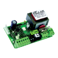
Connection of a pair of closing photocells, a pair of opening photocells and
a pair of opening/closing photocells
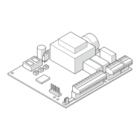
Connection of two pairs of closing photocells and two edge safety devices
Connection of two N.O. contacts in parallel
(e.g. Open A, Open B)
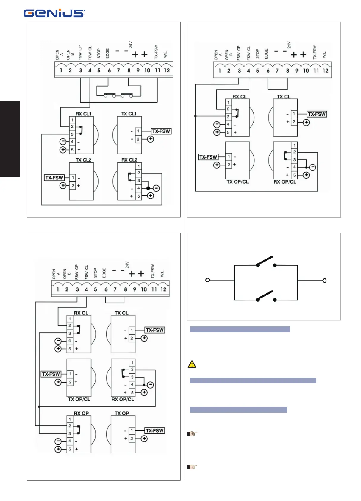
Connection of a pair of closing photocells and a pair of opening/closing
photocells
 Loading...