EasyManua.ls Logo

FAAC S450 User Manual

FAAC S450
34 pages
To Next Page IconTo Next Page
Page #1 background imageLoading...
Page #1 background image
24V Hydraulic Swing Gate Operator
UL325 - UL991
FAAC International Inc.
Headquarter & East Coast Operations
5151 Sunbeam Road
Suites 9-11
Jacksonville, FL 32257
Tel. (866) 925-3222
www.faacusa.com
FAAC International Inc.
West Coast Operations
357 South Acacia Avenue
Unit 357
Fullerton, CA 92831
Tel. (800) 221-8278
S450H
Question and Answer IconNeed help?

Do you have a question about the FAAC S450 and is the answer not in the manual?

FAAC S450 Specifications

General IconGeneral
Motor voltage24 Vdc
Power120 W
Type of limit switchMagnetic
UsageResidential
Power Supply230 Vac (50-60 Hz)
Operating Temperature-20°C to +55°C

Summary

IMPORTANT SAFETY INFORMATION

Important Safety Instructions

Key safety warnings for operating the gate operator.

Important Installation Instructions

Crucial guidelines for safe and correct gate operator installation.

GENERAL SAFETY PRECAUTIONS

Gate Construction

Standards for building and installing vehicular gates.

Installation Safety

Safety considerations during the gate operator installation process.

Usage Safety

Safe practices for operating the gate operator system.

UL325 GATE OPERATOR CLASSIFICATIONS

Residential Vehicular Gate Operator Class I

Operator class for single-family dwellings.

Commercial/General Access Vehicular Gate Operator Class II

Operator class for commercial and public access.

Industrial/Limited Access Vehicular Gate Operator Class III

Operator class for industrial and limited access locations.

Restricted Access Vehicular Gate Operator Class IV

Operator class for guarded and restricted access areas.

INSTALLING THE WARNING SIGNS

DESCRIPTION AND TECHNICAL SPECIFICATIONS

1.1 DIMENSIONS

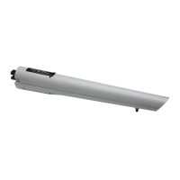
Provides physical dimensions of the gate operator system.

ELECTRICAL SETUP

INSTALLING THE OPERATOR

3.1 INSTALLATION DIMENSIONS AND APPLICATIONS

Specifies dimensions for bracket mounting to column and side wall.

3.2 OPERATOR INSTALLATION PROCEDURE

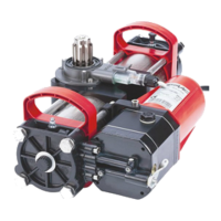
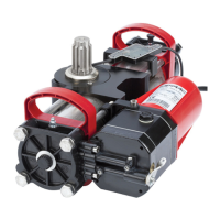
Step-by-step guide for physically installing the gate operator.

MANUAL OPERATION

ELECTRICAL CONNECTION OF THE ENCODER

BLEEDING

S450H PARTS DIAGRAMS

E024U CONTROL BOARD DESCRIPTION & CHARACTERISTICS

1.1 TECHNICAL SPECIFICATIONS

Technical data and specifications for the E024U control board.

1.2 LAYOUT AND COMPONENTS

Identification and description of control board components.

1.3 RADIO CONNECTION

Guidelines for connecting a radio receiver to the control board.

INPUT/OUTPUT DESCRIPTION

PHOTOCELLS CONNECTIONS

3.1 CONNECTIONS TO NORMALLY CLOSE (N.C.) PHOTOCELLS

Wiring diagrams for connecting NC photocells to the control board.

PROGRAMMING

4.1 DIP SWITCH DS1 SETTINGS FOR OPERATING LOGIC

Configuration of operating logic using DS1 dip switches.

4.2 ADJUSTING TRIMMERS

Details on adjusting force, speed, and pause time trimmers.

4.3 DIP SWITCH DS1 SETTINGS FOR BOARD SETUP

Configuration of board setup parameters using DS1 dip switches.

4.4 DIP SWITCH DS2 SETTINGS FOR OPERATOR TYPE AND LOCK MODE

Configuration of operator type and lock mode via DS2 dip switches.

LED DIAGNOSTICS

TIME LEARNING (SET-UP)

6.1 AUTOMATIC TIME LEARNING

Procedure for automatic learning of gate movement times.

6.2 MANUAL TIME LEARNING

Procedure for manual learning of gate movement times.

OBSTACLE DETECTION FUNCTION

ENCLOSURE

POWER CONNECTION

8.1 POWER SUPPLY

Details on the switching power supply for the control board.

BACKUP BATTERY

9.1 DISABLE THE BATTERY CHARGER

Instructions to disable the battery charging function.

FIRMWARE UPGRADE

FUNCTION LOGICS

LIMITED WARRANTY

Related product manuals