a
a
a a
x 1
Fig.12
Fig.13
Fig.15
Fig.14
1) Take the gate to its open position.
2) Consulting the instructions in chapter 7.1, hydraulically release
the operator, using the key (Fig. 1 ref. r ) on the release screw
(Fig. 12 ref. a)
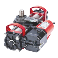
3) On the operator, unscrew the cap (Fig.13 ref.A) of the closing
travel-limit screw (Fig.13 ref. a) and check if the screw is
completely tight.
4) a
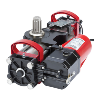
5) Turn the operator pinion with the supplied key,
as shown in Fig.14, up to the internal stop point
of the piston, and remove the key.
4.2 OPERATOR WITH MECHANICAL RELEASE
TRAVEL-LIMIT STOP
AT OPENING
TRAVEL-LIMIT STOP
AT CLOSING
6) , insert the supplied key on the
operator as shown in Fig.15, and make sure that it indicates 0
(ZERO) on the operator’s plastic panel (Fig.15 ref.a). If necessary
rotate the pinion.
.
NOTE: if necessary, lightly screw the closing travel-limit screw.
INSERT THE KEY WITHOUT MOVING THE PINION
AND CHECK IF IT INDICATES ZERO
TURN THE KEY TILL REACHING THE MECHANICAL
STOP-POINT AND WITHDRAW IT FROM THE PINION