Power line connection
6.
Ref.1912
· 235 ·
DDS
HARDWARE
TN diagram
Distribution diagram that has a point directly connected to ground and the
conductive parts of the installation are connected to this point through
ground protection conductors. This type of mains admits loads between one
or several phases and the neuter.
There are three kinds of TN diagrams depending on the relative position of
the neuter wire (N) and the protection wire (PE):
TN-S diagram where the neuter wire (N) and the protection wire (PE)
are different in the entire diagram.
TN-C-S diagram where the neuter and protection functions are
combined in a single wire (PEN) in part of the diagram.
TN-C diagram where the neuter and protection functions are combined
in a single wire (PEN) in the entire diagram.
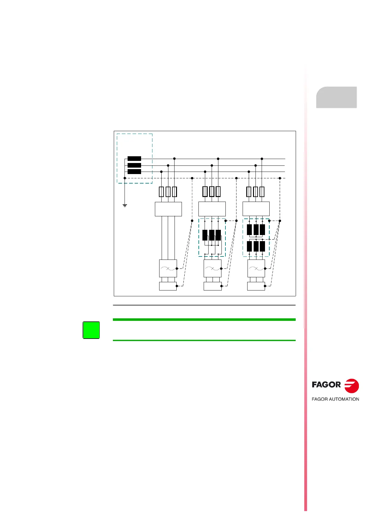
See figure
F. H6/4 for properly installing the DDS system with a TN-C type
distribution diagram.
F. H6/4
TN-C type distribution diagram.
DDSDDS
L1
L2
L3
DIFFERENTIAL
BREAKER
DDS
SECONDARY
WINDING OF THE
LINE TRANSFORMER
OF THE PLANT
DIFFERENTIAL
BREAKER
DIFFERENTIAL
BREAKER
MAINS
FILTER
PEN
MAINS
FILTER
MAINS
FILTER
INFORMATION. The DDS system may be connected directly, through a
transformer or auto-transformer in mains with a TN type distribution diagram.
 Loading...