Power line connection
6.
238
Ref.1912
DDS
HARDWARE
· 236 ·
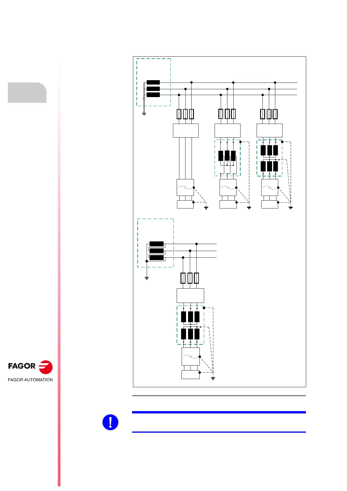
TT diagram
Distribution diagram that has a point directly connected to ground and the
conductive parts of the installation are connected to a ground point
independently from the ground electrode of the power supply system.
See figure
F. H6/5 for properly installing the DDS system in TT type
distribution network.
F. H6/5
TT type distribution diagram.
L1
L2
L3
DDS
DIFFERENTIAL
BREAKER
SECONDARY
WINDING OF THE
LINE TRANSFORMER
OF THE PLANT
MAINS
FILTER
DDSDDS
L1
L2
L3
DIFFERENTIAL
BREAKER
DDS
SECONDARY
WINDING OF THE
LINE TRANSFORMER
OF THE PLANT
DIFFERENTIAL
BREAKER
DIFFERENTIAL
BREAKER
MAINS
FILTER
MAINS
FILTER
MAINS
FILTER
The DDS system is designed
to support phase-chassis
voltages under 300 V AC.
It must be ensured that there is
no voltages over the indicated
value if an isolating
transformer is not installed; i.e.
if the DDS system is
connected directly to mains or
through an auto-transformer.
Otherwise, protection
elements must be installed to
avoid reaching excessive
voltages.
TT diagram
MANDATORY. ·CORNER GROUNDED· type TT mains require installing
an isolating transformer.
 Loading...