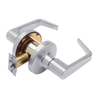
T-Series Service Manual
53
STEP 2
BORE HOLES: INSTALL LATCH
A. Bore a 267" (54mm) hole and two (2) 7RF" (8mm) holes
from both sides of door to avoid splintering wood.
B. Bore a 1" (25mm) hole into door edge. Using latch faceplate
as pattern, trace outline and mortise door edge so latch is flush
with door. If 7N projection latch is to be installed see Step 20.
Note: For wood jambs, close door and using a strike-locating tool
or other pointed object mark position of hole in jamb. Open door
and drill 1" (25mm) hole in jamb minimum 7N" (19mm) deep.
C. File two (2) 7;P" (4mm) x 7;P" (4mm) x 67" (3mm) deep notches
into both sides of door.
D. Insert latch unit in door, making certain that latch bolt bevel faces
direction of closing door. Attach with two #8 combination screws
provided.
Note: Use of a drill guide is recommended to ensure
straight and level holes.
IF USING THE FALCON OPTIONAL DRILL GUIDE
Install Drill Guide (030736-000-70) into door. Make certain correct backset
locators are even with door edge. Drill two (2) 7RF" (8mm) holes from both
sides to center.
Note: Drill guide replacement is recommended after 10 door preparations.
When drilling through door, be careful not to damage door finish.
STEP 3
INSTALL CHASSIS AND OUTER TRIM ASSEMBLY
Note: For ease of installation, lock should be in
the unlocked position.
Slide chassis assembly into door from outside
making sure that lock housing engages latch
prongs. Retractor must also engage latch tail.
Important: Chassis assembly must be positioned
in center of door for proper operation.
STEP 4
INSTALL INNER MOUNTING PLATE
A. Place inner mounting plate onto chassis assembly
making sure that plate tabs engage horizontal
notches in door.
B. Position flanged nut over chassis assembly and
tighten securely with hex wrench provided.
Lock Housing
Latch Prong
Latch Tail
Retractor
Latch Case
Chassis Assembly
Outside of Door
Notches
Tab
Flanged Nut
Black Hex Wrench Chassis Assembly
Tab
Inner Mounting Plate
A) 5/16" (8mm)
Thru hole
C) File Notches
B) 1" (25mm) Hole
5/32"
Latch
Bolt Bevel
Latch Unit
A) 2-1/8" (54mm)
Thru hole
A) 5/16" (8mm)
Thru hole
Use faceplate as pattern for mortise.
Backset
Locator

 Loading...