39
Figure 63
Calibrations should be preformed regularly on the 400
in accordance with the method. Refer to each method
for it is required calibration schedule. Calibrations should
be performed on the heater tube thermocouple, the dif-
ferential pressure transducer and the system pressure.
‘Thermocouple’ allows for a calibration of the temperature
control system using ice and the eutectic temperature of
lead to calibrate the heater tube thermocouple. The dif-
ferential pressure is the measurement across the DP test
filter. Excessive differential pressure (DP) is an indication
of poor fuel quality. ‘Diff Press’ provides a calibration of
the differential pressure transducer. ‘Sys Press’ allows for
adjustment of the pressure measurement against a NIST
certified reference pressure gauge.
7.1 Thermocouple
The auto calibration performs a calibration of the heater
tube thermocouple by a ‘low’ calibration check using an
ice bath and a ‘high’ calibration procedure using the lead
calibration assembly. It is critical that the following steps
be followed carefully. Failure to have the thermocouple in
the correct position during each step can cause the unit
to continue to apply heat to the bus bars or fail to heat the
bus bars. Should a step not complete as documented
within seven minutes of initiation, shut the unit off
from the power switch on the front, allow the unit to
cool for a minimum of 20 minutes before restoring
power and re-initiating calibration.
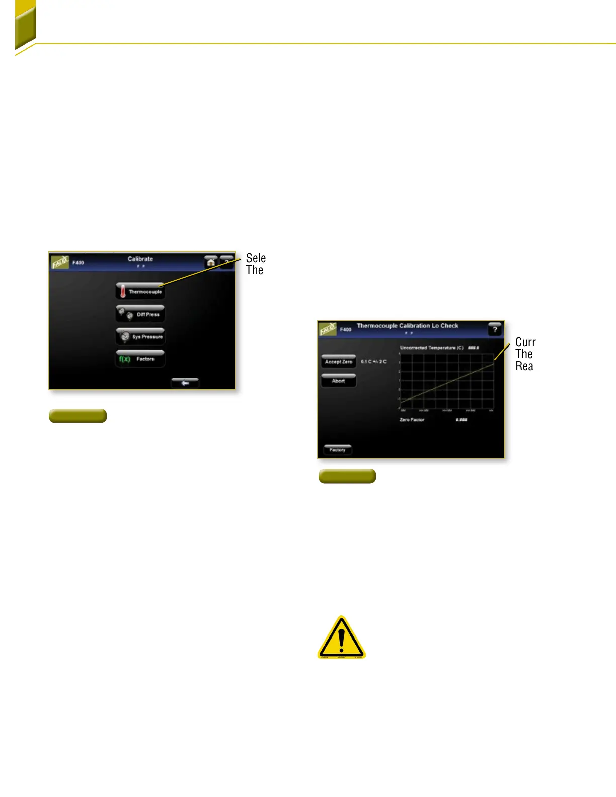
1. [Figure 63] From the Main Menu, go to the
Maintenance > Calibrate > Thermocouple display.
This will reset the previous calibration factors to the
default values (0 ºC factor = 0 and 327.5 ºC factor
= 327.5). It will also call up the ‘Thermocouple
Calibration Lo Check’ display.
Section 7: Calibration
7.1.1 Thermal Calibration Lo Check
1. Prepare a low temperature standard, from an ice
bath of distilled water and crushed distilled water
ice (an insulated cup works best).
2. Place the heater tube thermocouple in the
icebath.
3. Stir the thermocouple in the bath watching the
tube temperature on the display [Figure 64].
4. Continue stirring until the tube temperature no
longer drops and holds constant for 20–30
seconds. Press the ‘Accept’ button. This will
store the observed low temperature and will
initiate the Thermocouple Hi Check display. The
thermocouple reading should be accepted if
the displayed value is 0.1˚C ±2˚C. Should the
thermocouple not reach this value, verify the ice
bath is not contaminated. If it still will not reach an
acceptable value, replace the thermocouple.
7.1.2 Thermocouple Calibration
Hi Check
1. Install the lead calibration check assembly in the
upper/lower bus bars. Make sure the top of the
assembly is flush with the top of the upper bus bar
and that the bus bar screws are tight.
Manual insertion and removal of the
thermocouple is required during the Hi
Check. Care should be taken during all
steps as the bus bars are extremely hot
and can carry high current. Only insert
and remove the thermocouple by the
insulatedleads.
2. Insert the heater tube thermocouple through
the top bus bar into the assembly so that the
thermocouple is in contact with the lead.
Figure 64
Thermocouple Lo
Check Screen
Current
Thermocouple
Reading
Select
Thermocouple