42
Section 8: Service
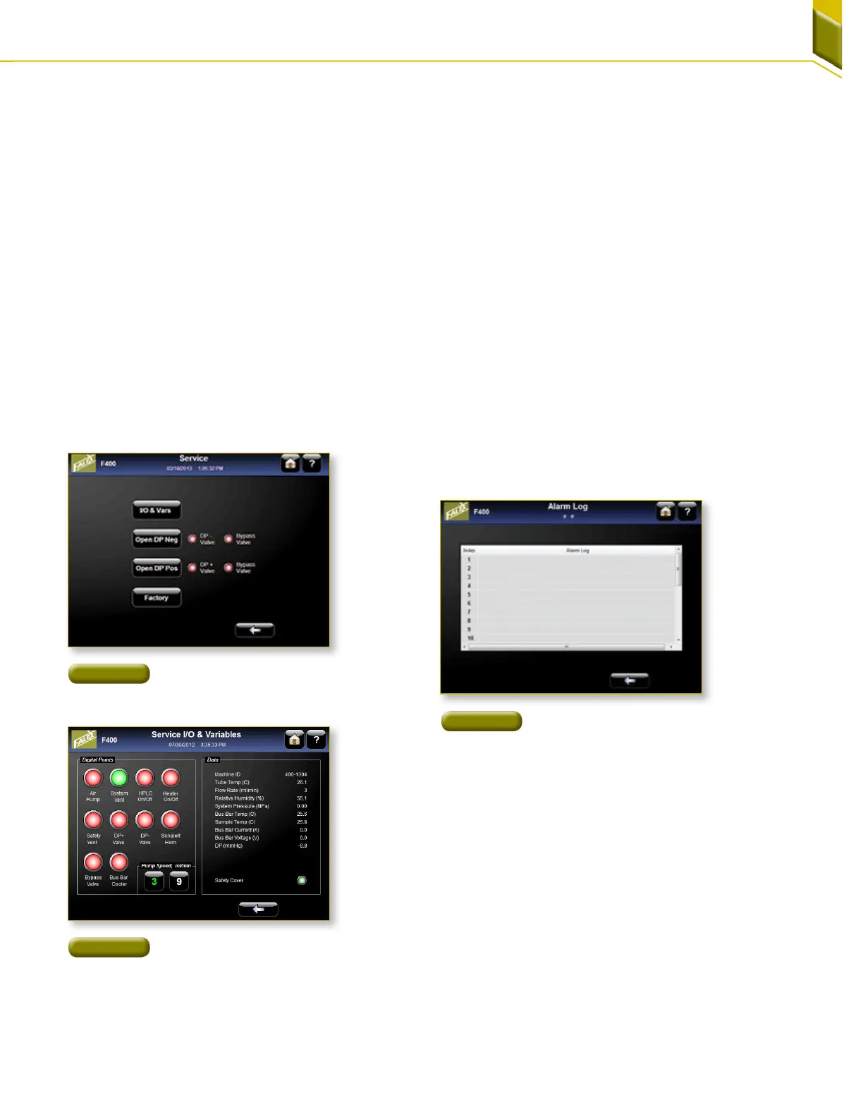
8.1 Software Accessible Service
Obtaining manual access to machines functionalities is
done through the ‘Service’ screen accessed from the
maintenance screen [Figure 70]. The user has access to
various controls so operation should only be undertaken
by someone with understanding of the system.
1. I/O & Vars: [Figure 71] Manual operation of different
controls can be accessed by pressing the large
green or red buttons under Digital Points. The
HPLC pump can manually be set to flow at either 3
or 9 ml/min for this service screen. Live feedback is
shown in the Data section of this screen.
2. Close DP Neg: Pressing this button manually
operates the DP negative valve. This button
is not interlocked with the bypass valve and
should be used only if the operator has an
understanding of the system as not to damage the
pressuretransducer.
3. Close DP Pos: Pressing this button manually
operates the DP positive valve. This button is not
interlocked with the bypass valve and should be
used only if the operator has an understanding
of the system as not to damage the pressure
transducer.
4. Factory: This is a protected area for the authorized
users only.
8.2 Alarm Log
[Figure 72] Pressing the alarm log button displays the last
25 warnings and abort alarms.
8.3 Fault Indicators
On the front of the Falex 400 are 17 indicator lights. If
a fuse trips an indicator light will be visible with the
description of the problem area. Cycle the power on the
unit and restart the procedure that caused the fault. The
fuse should have reset. If the indicator light comes on
again, contact the Falex service department.
Figure 70
Service Screen Reached From
The Maintenance Screen
Figure 72
Listing of most current alarms
Figure 71
I/O & Variable Screen