1: General Information
10
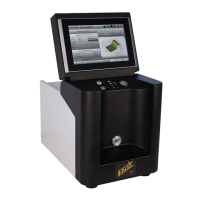
Figure 1-3 – Control Panel
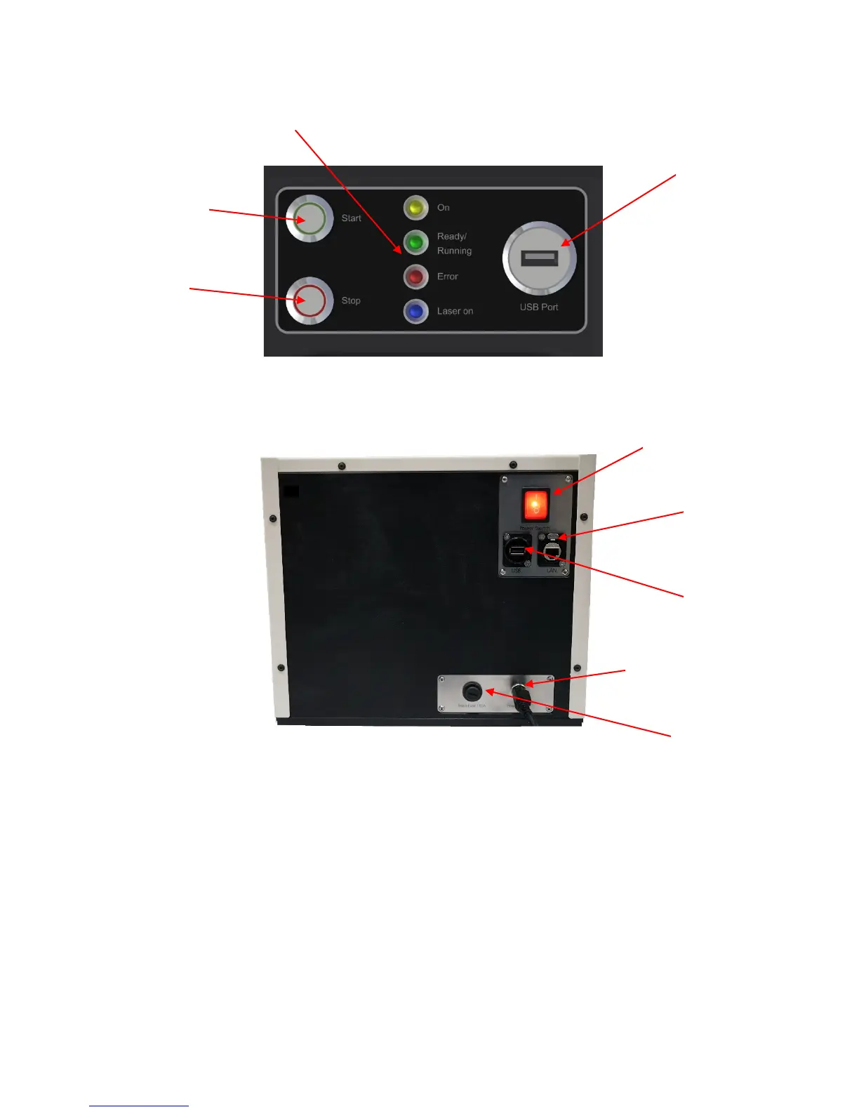
Figure 1-4 – Cabinet (back)
The Falex 430 ETR has the following features:
User Interface: A touch screen computer is located on the top of the electronic cabinet and is used
as the user interface for configuration, control, and monitoring of the test.
Automatic Tube Alignment: Internal positioning allows for consistent heater tube alignment and
also compensates for warped or slightly bent tubes.
Heater Tube Inlet: Allows access to heater tube loading assembly for positioning of the heater tube.
Control Panel: Consists of measurement process start/stop push-buttons, machine status indicators
and data transfer USB port.
Supply Connection
Connection