
М
Мурат КайымJun 21, 2025
мне нужно файл прошивки для изменения языка на русский
мне нужно файл прошивки для изменения языка на русский
Instructions and precautions for safe operation of the cutting machine system.
Specifies environmental requirements, operational guidelines, and maintenance advice.
Crucial safety precautions related to high voltage hazards during operation.
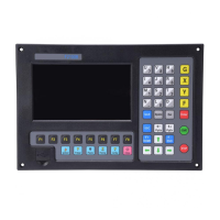
Introduces the F2000 series system and lists its various models.
Lists key features, technical indicators, and interface details of the F2000 system.
Outlines hardware components for different F2000 models.
Explains the layout and components of the system operation boards.
Details the system startup process and the main interface screen.
Provides a flowchart of main interface functions and access paths.
Lists functions available in the cutting interface and their key assignments.
Details forward, backward, edge cutting, and speed regulation functions.
Covers reference return, preheat, perforation selection, and frame functions.
Covers wiring, settings, and operation of the Arc THC module for height control.
Mirroring, starting point selection, and angle adjustment for cutting graphics.
Arranging parts in array formats and selecting rows/numbers for cutting.
Zooming graphics and reverting all part option changes to the original state.
Describes fixed, continuous, and fixed-length manual movement functions.
Procedures for recovering from a paused state or power failure to resume cutting.
Managing local and U disk files, including searching, editing, and creating.
Managing work folders and clearing system files.
Common, Flame, Plasma, and Powder parameters for different cutting processes.
System parameters, import, export, and saving of parameters.
Overview of diagnosis interface, input/output, keyboard, and self-check functions.
Setting date/time, system definition, parameter management, IO/coordinate, motor, language, and updates.
How to select graphics from the library and adjust film/hole sizes.
Explains programming symbols and their meanings used in cutting codes.
Details coordinate systems and explains G-codes and M-codes for operation.
Details input ports, signal definitions, wiring, and remote controller input.
Explains output ports and their wiring for various cutting functions.
Wiring diagrams for connecting motor drivers to the system.
Interface and wiring details for the Arc THC module.
Instructions for connecting the system's power supply.
Steps to upgrade system software and welcome interface.
Procedures for backing up and restoring the system to a previous state.
How to set horizontal/vertical pulse numbers for axis calibration.
Overview of the wireless remote control module's performance and characteristics.
Layout, output ports, and jumper switch interpretation for the remote controller.
Wiring diagram for connecting the remote controller to the CNC system.
Timing sequence diagram for flame cutting operations.
Timing sequence diagrams for plasma cutting operations.
Wiring diagram for connecting F1620/F1630 THC controllers.
Wiring diagram for connecting HYD THC controllers.
Wiring diagram for connecting SH-HC30 THC controllers.
Wiring diagram for connecting ONTIME THC controllers.
Wiring diagram for connecting PTHC-2 THC controllers.
Installation dimensions for the F2100B/T series.
Installation dimensions for the F2200B/T series.
Installation dimensions for the F2300A/B/T series.
Installation dimensions for the F2500A/B/T series.
Installation dimensions for the F2600/T series.
Contact details and directions for the Shanghai office.
| Display | LCD |
|---|---|
| Number of control axes | 2 |
| Drive mode | Stepper motor |
| Input voltage | 220V |
| Maximum speed | 24m/min |