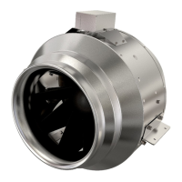
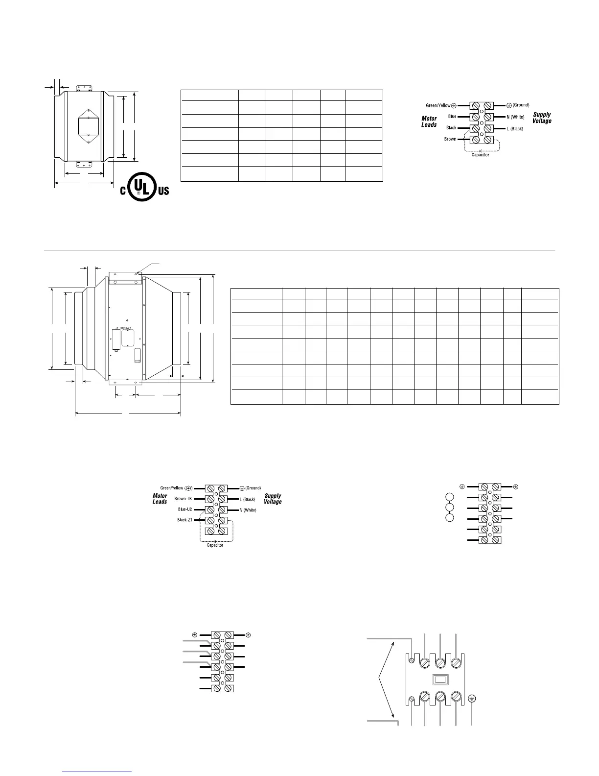
Dimensions and Wiring (Models FKD 8XL,10, 10XL,12S, 12,14S)
Model A C D E Weight
FKD 8XL 8 12¹⁄₂ 15¹⁄₂ 7 19 lbs.
FKD 10 10 12¹⁄₂ 12¹⁄₂ 7 21 lbs.
FKD 10XL 10 14 15 8 15 lbs.
FKD 12S 12 12¹⁄₂ 10 7 22 lbs.
FKD 12 12 14 12¹⁄₂ 8 16 lbs.
FKD 14S 14 14 † 816lbs.
Dimensional Data
All dimensions in inches. † FKD 14s
overall length is 8”
3⁄4”
115 Volt Single Phase Fans
Dimensions and Wiring (Models FKD 12XL,14, 14XL,16, 16XL,18, 18XL,20)
Dimensional Data
All dimensions in inches. † FKD 14s
overall length is 8”
Model A A1 A2 B B1 C D E F G H Weight
FKD12XL 12 - 12 17⁷⁄₈ 20¹⁄₄ 18⁷⁄₈ ⁷⁄₈ 1⁵⁄₈ 4 7³⁄₄ ³⁄₈ 45 lbs.
FKD14 14 - 14 19³⁄₄ 22¹⁄₈ 20¹⁄₄ 1¹⁄₂ 1⁵⁄₈ 4 11¹⁄₈ ³⁄₈ 45 lbs.
FKD14XL 14 - 14 19³⁄₄ 22¹⁄₈ 20¹⁄₄ 1¹⁄₂ 1⁵⁄₈ 4 11¹⁄₈ ³⁄₈ 55 lbs.
FKD16 16 16 - 19³⁄₄ 22¹⁄₈ 18¹⁄₄ 1¹⁄₂ 1⁵⁄₈ 4 9¹⁄₂ ³⁄₈ 55 lbs.
FKD16XL 16 - 16 22¹⁄₈ 24³⁄₈ 23¹⁄₄ 1¹⁄₄ 1⁵⁄₈ ⁷⁄₈ 8¹⁄₂ ¹⁄₂ 85 lbs.
FKD18 18 18 - 22¹⁄₈ 24³⁄₈ 21³⁄₄ 1¹⁄₄ 1⁵⁄₈ ⁷⁄₈ 7 ¹⁄₂ 85 lbs.
FKD18XL 18 - 18 28¹⁄₈ 30³⁄₈ 30⁵⁄₈ 2 1³⁄₄ ⁷⁄₈ 12¹⁄₂ ¹⁄₂ 95 lbs.
FKD20 20 20 - 28¹⁄₈ 30³⁄₈ 30⁵⁄₈ 2 1³⁄₄ ⁷⁄₈ 10¹⁄₂ ¹⁄₂ 95 lbs.
115/230 Volt Single Phase Fans
Wiring schematic for 4 lead motors,single phase
Notes:
1. All leads are color coded
as well as identified with an
Alpha/Alpha or Alpha /
Numeric code (i.e.TK or
Z2).This code may be
shown as a band on the
wire or on a schematic on
the motor hub.Colors
should be verified against code band.If code band and color do not
correspond to schematics above,wire according to the code on the band.
2. Color of capacitor leads may be reversed.Fan operation will not be
affected.
230 Volt Three Phase Fan
Notes:
1. Contactor should be used.
Control coil should be
wired in series with motor
thermal contacts (TK
leads) as shown in diagram
to provide thermal motor
protection.
2. All leads are color coded
as well as identified with a band containing an Alpha/Alpha or
Alpha/Numeric code (i.e.TK or Z2).Colors should be verified against code
band.If code band and color do not correspond to schematics above,wire
according to the code on the band.
Motor
Leads
W2
U2
V2
(Ground)
Line 1
Line 2
Supply
Voltag
U1
V1
W1
TK
TK
Green/Yellow ( )
Line 3
460 Volt Three Phase Fan
Notes:
1. Contactor should be used.
Control coil should be wired
in series with motor thermal
contacts (TK leads) as shown
in diagram to provide thermal
motor protection.
2. All leads are color coded as
well as identified with a band
containing an Alpha/Alpha or Alpha/Numeric code (i.e.TK or Z2).Colors
should be verified against code band.If code band and color do not
correspond to schematics above,wire according to the code on the band.
Contactor for 3-Phase Fans, 208-230/460v
Motor
Leads
(Ground)
Line 1
Line 2
Supply
Voltag
U1
V1
W1
TK
TK
Green/Yellow ( )
Line 3
W2
U2
V2
L1
Incoming
3-Phase Supply 208/230/460
Control Power
for Contactor
AC Contacto
L2 L3
TK TK L1 L2 L3 L3
Ground
T1 T2 T3
C1
C2
Motor Leads
C
A
E
D
H
B1
B
A
F
G
C
A1
A2
D
D
Call 1-800-667-8721 anywhere in the US and Canada
- www.rangehoods.com
Fan Tech at
kitchen
::
accessories
U N L I M I T E D
::
rangehoods
.com