40
8 GbD-02
P3
6
P2
P1
7
5
3
2
1
P2
P3
6
P1
7
5
3
2
1
P1
P3
P2
6
7
5
3
2
1
CT4
+SP
CT3
+SP
CT2
+SP
CT1
+SP
x2
x3
6
P3
P2
P1
7
5
3
2
1
3
2
1
xn
6
P1
7
5
3
2
1
P1
6
7
5
3
2
1
CT2
CT1
x2
1
6
P2
P1
7
5
3
2
1
P2
6
P1
7
5
3
2
1
P1
P2
6
7
5
3
2
1
CT3
+SP
CT2
+SP
CT1
+SP
x2
xn
2
1
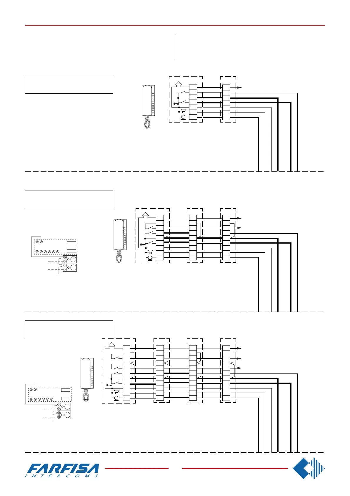
WORKING DIAGRAMS FOR INTERCOMMUNICATING SYS-
TEMS WITH A DOOR STATION AND INDIVIDUAL CALL.
Combine with the system Si 210/5.
2 intercommunicating intercoms
2 Gegensprechhaustelefone
ANWENDUNGSSCHALTPLÄNE FÜR MEHRFAMlLIENHAUS
GEGENSPRECHANLAGEN MIT TÜRSTATION.
Kombinierbar mit dem Schaltplan Si 210/5.
4 intercommunicating intercoms
4 Gegensprechhaustelefone
3 intercommunicating intercoms
3 Gegensprechhaustelefone
Connect one of the two terminals of the single button unit
to terminal 7.
Eine Anschlußklemme der Zusatztasten muß mit der
Klemme 7 verbunden werden.
Connect one of the two terminals of the single button unit
to terminal 7.
Eine Anschlußklemme der Zusatztasten muß mit der Klem-
me 7 verbunden werden.
9 7
2315P16
P2
P3
9 7
2315P16
P2
P3