33
8 GbD-02
G2 7
AD
C+
+
P3
P4
6
P2
P1
7
5
3
2
1
P2
P4
P3
6
P1
7
5
3
2
1
P1
P4
P3
P2
6
7
5
3
2
1
6
P4
P3
P2
P1
7
5
3
2
1
P4
6
P3
P2
P1
7
5
3
2
1
CT4
+SP
CT5
+SP
CT3
+SP
CT2
+SP
CT1
+SP
230V
0
127V
AL
SE
4
3
2
1
xn
x4
x3
x2
1
2
3
4
PE
xn
x2
MD
PA
Mody
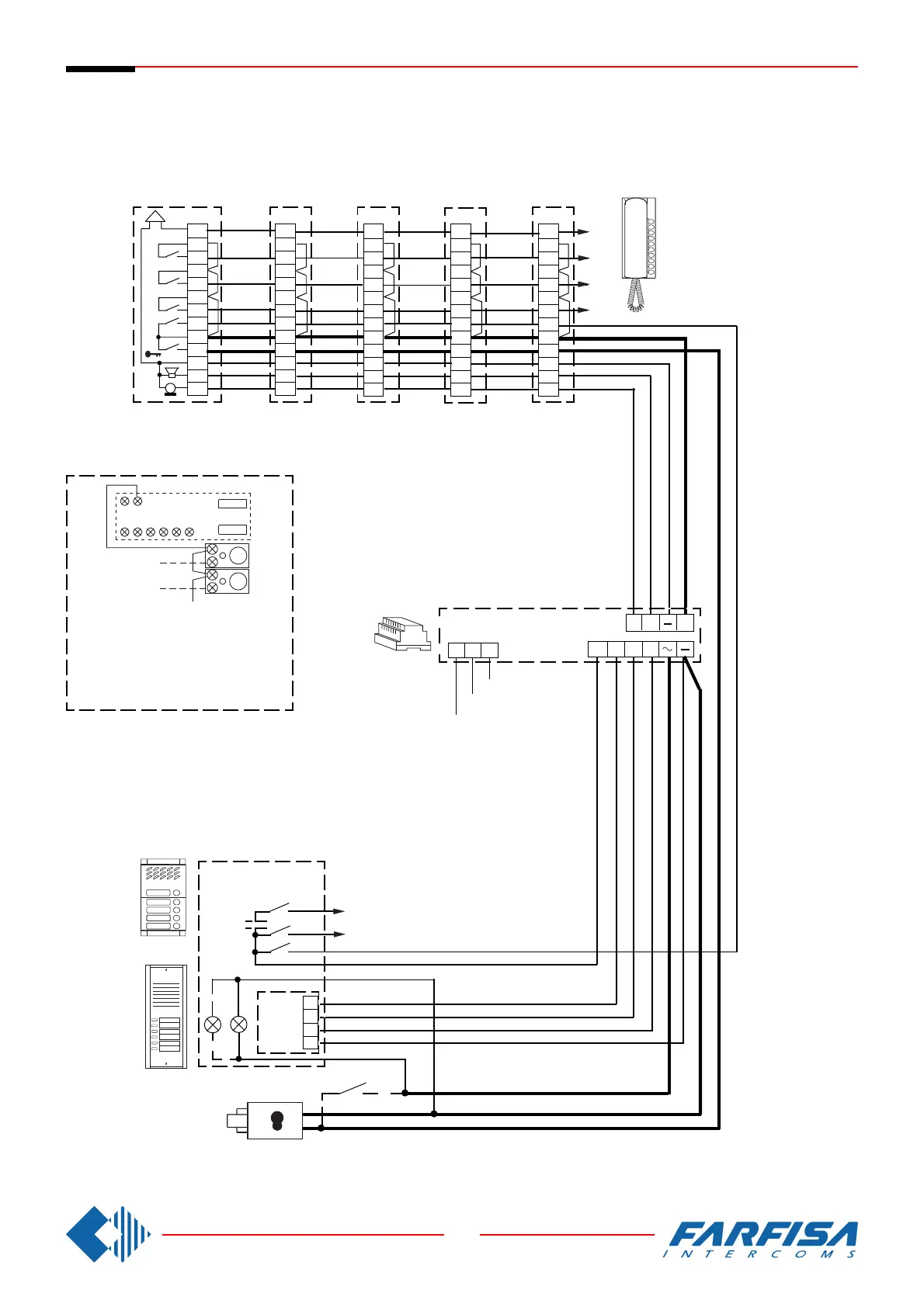
In all intercoms connect one of the two
terminals of the single button unit to
terminal 7.
In allen Haustelefonen muß eine der
Anschlußklemmen der Zusatztasten mit
der Klemme 7 verbunden werden.
Intercommunicating
Gegensprechanlagen
Si 210/5
5 INTERCOMMUNICATING INTERCOMS CONNECTED TO A DOOR STATION
WITH INDIVIDUAL CALL.
MEHRFAMILlENHAUS SPRECHANLAGE MIT 5 HAUSTELEFONE, EINER
TÜRSTATION UND INTERNEN GEGENSPRECHVERKEHR.
ErreP/R