39
8 GbD-02
P3
P4
P2
P1
7
5
6
3
2
1
P2
P4
P3
P1
7
5
6
3
2
1
P1
P4
P3
P2
7
5
6
3
2
1
P4
P3
P2
P1
7
5
6
3
2
1
P4
P3
P2
P1
7
5
6
3
2
1
CT4
+SP
+RS
CT5
+SP
+RS
CT3
+SP
+RS
CT2
+SP
+RS
CT1
+SP
+RS
4
3
2
1
xn
x4
x3
x2
230V
0
127V
AL
G2 7
C+
DA +
98753
6
7a
8a
9a
1
2
3
4
1
2
3
4
4
2
1
7b
8b
9b
PE
DS
PA
PA
PE
SE
SE
x2
x2
xn
" a "
xn
MD
MD
" b "
Mody
ErreP/R
ErreP/R
Mody
Intercommunicating
Gegensprechanlagen
Si 250/5
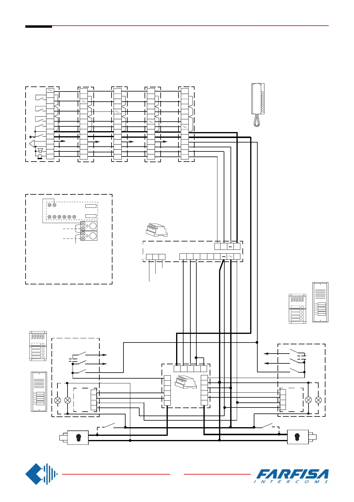
5 INTERCOMMUNICATING INTERCOMS CONNECTED TO TWO DOOR
STATIONS WITH AUTOMATIC SWITCHING AND WITH INDIVIDUAL CALL.
ELECTRONIC BELL FOR INTERNAL CALLS.
MEHRFAMILIENHAUS SPRECHANLAGE MIT 5 HAUSTELEFONE, 2 UMSCHALTBARE TÜR-
STATIONEN UND INTERNEN GEGENSPRECHVERKEHR MIT ELEKTRONISCHEM KLANG-
RUF FÜR INTERNRUFE.
In all intercoms connect one of the two
terminals of the single button unit to
terminal 7.
In allen Haustelefonen muß eine der
Anschlußklemmen der Zusatztasten mit
der Klemme 7 verbunden werden.