Controls for re-entry of the outriggers for crane and supplementary
beam to within the overall vehicle width, after crane use
–
Position lever D of the oil-diverter crane-outriggers
( - E/S) on E/S.
Fig. 22.
–
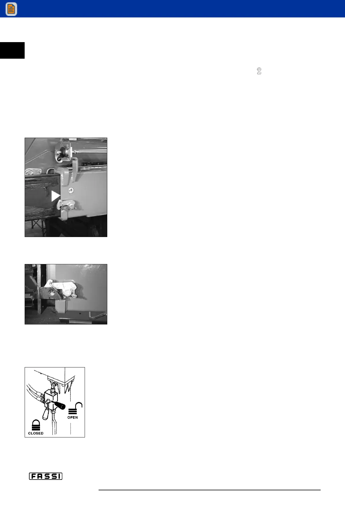
Open all the valve taps placed on the outrigger rams
(fig. 17).
(!)
WARNING
(!)
Never put your hands on the locking devices of the outrigger supports; the
re-hooking of the device (lever A from the pos. indicated on fig. 25b to the
one indicated on fig. 25) is automatic.
–
Select the outrigger ram S1 positioning lever C on S1.
–
Operate the lever to control the re-entry of the ram S1.
–
Select the outrigger support E1 positioning lever C on E1.
–
Operate the lever to obtain the re-entry of the support E1.
–
Select the ram S2 positioning lever C on S2.
–
Operate the lever to control the re-entry of the ram S2.
–
Select the support E2 positioning lever C on E2.
–
Operate the lever to obtain the re-entry of the support E2.
–
Select the ram S3 positioning lever C on S3.
–
Operate the lever to control the re-entry of the ram S3.
–
Select the support E3 positioning lever C on E3.
–
Operate the lever to obtain the re-entry of the support E3.
–
Select the ram S4 positioning lever C on S4.
–
Operate the lever to control the re-entry of the ram S4.
–
Select the support E4 positioning lever C on E4.
–
Operate the lever to obtain the re-entry of the support E4.
(!)
Always check that the outrigger supports, once in their rest
position, are locked in their seat by the safety devices, so as
to assure the impossibility of accidental movements
(Fig. 25).
(!)
It is compulsory to close the outrigger ram valve taps before
moving the truck
(fig. 17).
c IX
CONTROLS
TO STABILIZE
THE VEHICLE
F 240
22
fig. 25
fig. 25b
fig. 17