1-5
1.3 Ladder Diagram Structure and Terminology
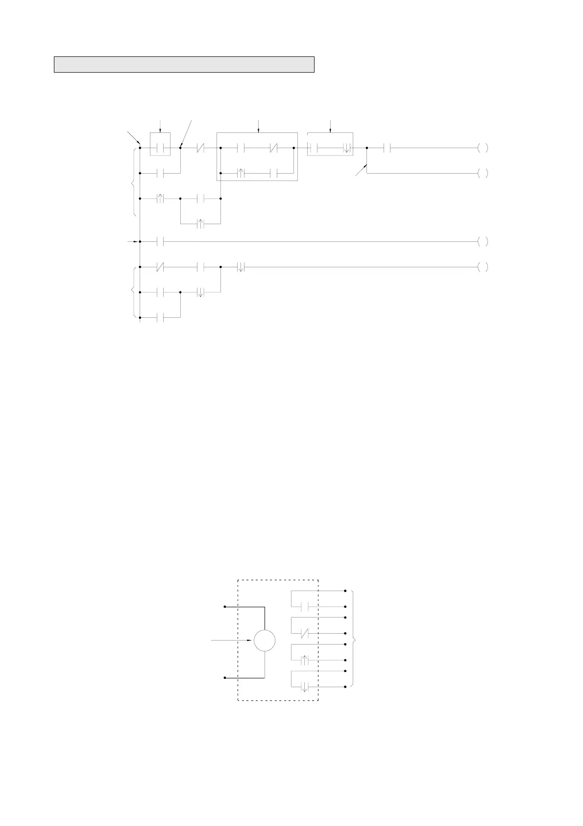
Sample Ladder Diagram
Y4
X11
X14
M6Y0
X16
X10
X12
M1
X20
X1X0
X7
X10
X2
X9
X3
X4 X5 X6
/
Y4
Y5
/
Y2
Y0
Serial blockParallel blockNodeElement
Origin line
Network 1
Network 2
Network 3
Branch
(Remark:The maximum size of FBs-PLC network is 16 rows×22 columns)
As shown above, the Ladder Diagram can be divided into many small cells. There are total 88 cells (8 rows X 11 columns)
for this example Ladder Diagram. One cell can accommodate one element. A completed Ladder Diagram can be formed by
connecting all the cells together according to the specific requirements. The terminologies related to Ladder Diagram are
illustrated below.
c Contact
Contact is an element with open or short status. One kind of contact is called "Input contact"(reference number prefix with X)
and its status reference from the external signals (the input signal comes from the input terminal block). Another one is
called "Relay contact" and its status reflects the status of relay coil (please refer to
d). The relation between the reference
number and the contact status depends on the contact type. The contact elements provided by FB series PLC include: A
contact, B contact, up/down differential (TU/TD) contacts and Open/Short contacts. Please refer to
f for more details.
d Relay
Same as the conventional relay, it consists of a Coil and a Contact as shown in the diagram below.
Relay coil
Y0
COIL
Y0
Y0
Y0
Y0
A
B
TU
TD
Relay contacts
Y5
X5
X4
X6
Y0
Y2
Y4
X3X2
X9
X10
Branch
Serial block
Parallel block
X1
X7
Y4
X10
X11
Origin line
Node
Element
Network 1
X0
M6
M1
Y0
X12
X20
X16
Network 2
Network 3
X14