1-6
We must energize the coil of relay first (using OUT instruction) in order to turn on the relay. After the coil is energized, its
contact status will be ON too. As shown in the example above, if Y0 turns ON, then the relay contact A is ON and contact B
is OFF, TU contact only turns ON for one scan duration and TD contact is OFF. If Y0 turns OFF, then the relay contact A is
ON and contact B is ON, TU contact is OFF and TD contact only turns ON for one scan duration (Please refer to chapter 5
“Introduction to Sequential Instructions” for operations of A,B,TU and TD contacts).
There are four types of FB-PLC relays, namely Y△△△(output relay), M△△△△(internal relay), S△△△(step relay)
and TR△△(temporary relay). The statuses of output relays will be sent to the output terminal block.
e Origin-line: The starting line at the left side of the Ladder Diagram.
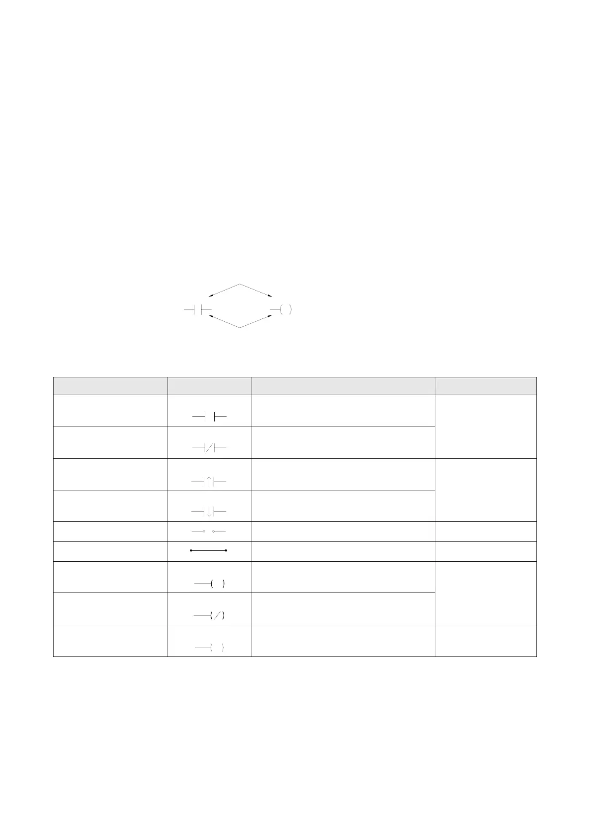
f Element: Element is the basic unit of a Ladder Diagram. An element consists of two parts as shown in the diagram below.
One is the element symbol which is called “OP Code” and another is the reference number part which is called
“Operand”.
Operand
X100
Y15
OP Code
Element type Symbol Mnemonic instructions Remark
A Contact
(Normally OPEN)
□△△△△
(ORG、LD、AND、OR) □△△△△
B Contact
(Normally CLOSE)
□△△△△
(ORG、LD、AND、OR) NOT
□△△△△
□ can be X、Y、M、S、
T、C(please refer to
section 3.2)
Up Differential Contact
□△△△△
(ORG、LD、AND、OR) TU
□△△△△
Down Differential Contact
□△△△△
(ORG、LD、AND、OR) TD
□△△△△
□ can be X、Y、M、S
Open Circuit Contact
(ORG、LD、AND、OR) OPEN
Short Circuit Contact
(ORG、LD、AND、OR) SHORT
Output Coil
□△△△△
OUT □△△△△
Inverse Output Coil
□△△△△
OUT NOT □△△△△
□ can be Y、M、S
Latching Output Coil
Y△△△
L
OUT L Y△△△
Remark:please refer to section 3.2 for the ranges of X、Y、M、S、T and C contacts. Please refer to section 5.2 for the
characteristics of X、Y、M、S、T and C contacts.
There are three special sequential instructions, namely OUT TRn, LD TRn and FOn, which were not displayed on the
Ladder Diagram. Please refer to section 1.6 “Using the Temporary Relay” and section 5.1.4 “Function Output FO”.