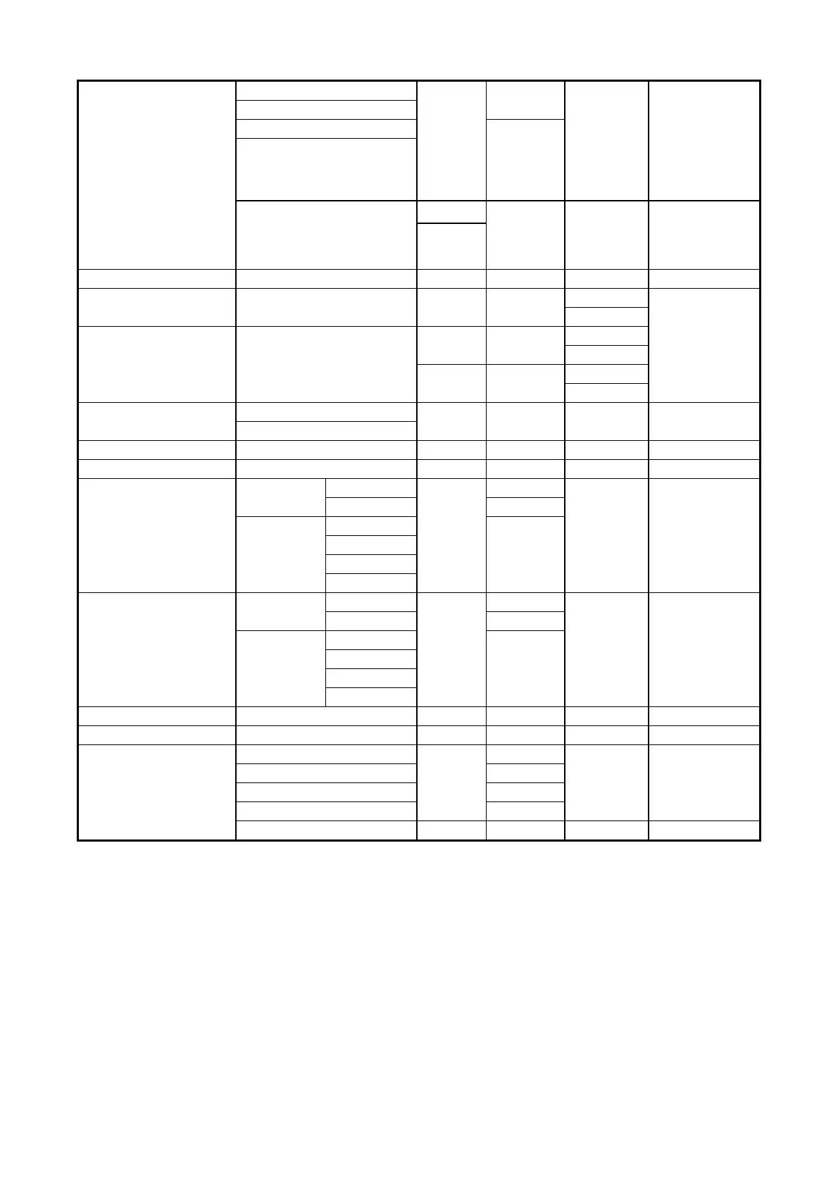
H3-4
FBs-B2A1D
VI0(V)
1
The voltage and
current inputs can’t
be used at the
same time in the
same channel. It
only one (V or I)
available.
II0(I)
VI1(V)
1
II1(I)
VO0(V)
1
Both voltage and
current will be
outputted at the
same time.
IO0(I)
FBs-32DGI Unlabeled 8 1 CH only
FBs-7SG1 CH0
3(D)
D:decode mode
ND : non-decode
mode
4(ND)
FBs-7SG2
CH0
3(D)
4(ND)
CH1
2(D)
4(ND)
FBS-2TC
CH0
1 1 CH only
CH1
FBs-6TC/6RTD CH0~CH5 1 1 CH only
FBs-16TC/16RTD CH0~CH15 1 1 CH only
FBs-2A4TC
2A
CH0
1
CH1 1
4TC
CH0
2
CH1
CH2
CH3
FBs-2A4RTD
2A
CH0
1
CH1 1
4TC
CH0
2
CH1
CH2
CH3
FBs-6NTC CH0~CH5 1
FBs-1LC CH0 1
FBs-4PT
CH0
1
CH1 1
CH2 1
CH3 1
1 Or unused
The corresponding IR or OR number calculation of the NI/O module starts from the first expansion unit/module(main
unit itself does not have any NI/O). The first NI channel corresponds to the first IR register (R3840). Adding R3840 with
the number of IR used by the first NI channel gives the IR number of the second NI channel. Adding the IR number of
the second NI channel with the number of IR used by the second NI channel gives the IR number of the third NI
channel. All other numbers can be obtained accordingly. Similarly, the first NO channel corresponds to the first OR
(R3904). Adding R3904 with the number of OR used by the first NO channel gives the OR number of the second NO
channel. (In the cumulative calculation of NI channels, care only for NI channels and disregard DI/O and NI. Similarly,
in the case of NO channels, disregard DI/O and NI channels.) The following figure helps users find out the relation
between NI/O channels and PLC’s IR and OR.