H3-5
6547
IN X
OUT Y
Y3
98
Y4
C4
Y5
C6
I20
546
POW
RX
ERR
RUN
I3I2
98
I0
Y8Y6
Y7 Y9
3
7
( )
( )
I I
X6X4
X5
0I2
X7
X12
X10
X8
3
X9
X11
X13
Non-Decode
mode
Decode mode
(R3906~8)
CH0 or
(R3906~9)
CH1 (R3849)
CH0 (R3848)
CH0 (R3904)
CH1 (R3905)
I
I
IR
IR
(R3840)
|
(R3847)
CH4 (R3852)
CH3 (R3851)
CH2 (R3850)
CH5 (R3853)
I1+
I5+
POW
I3+I2+
I2-
I4+
I3-
I4-
POW
24V IN
5VV UI B
I0+
10V
AG I0-
POW
I5-
Y1
O0+
I
I1-
V
24V IN
BU 5V 10V
AG
O1+
O0- O1-
X1
S/S
(R3909~10)
CH1 |
(R3910~13)
OR
POW
Y4
Y2
C1
Y3
C3
4
( )
OUT Y
32
4
IN X
( )
23
POWPOW
CH1
EXT
POW
VV
01
X3
X2 X4
CH0
IR
OR
OR
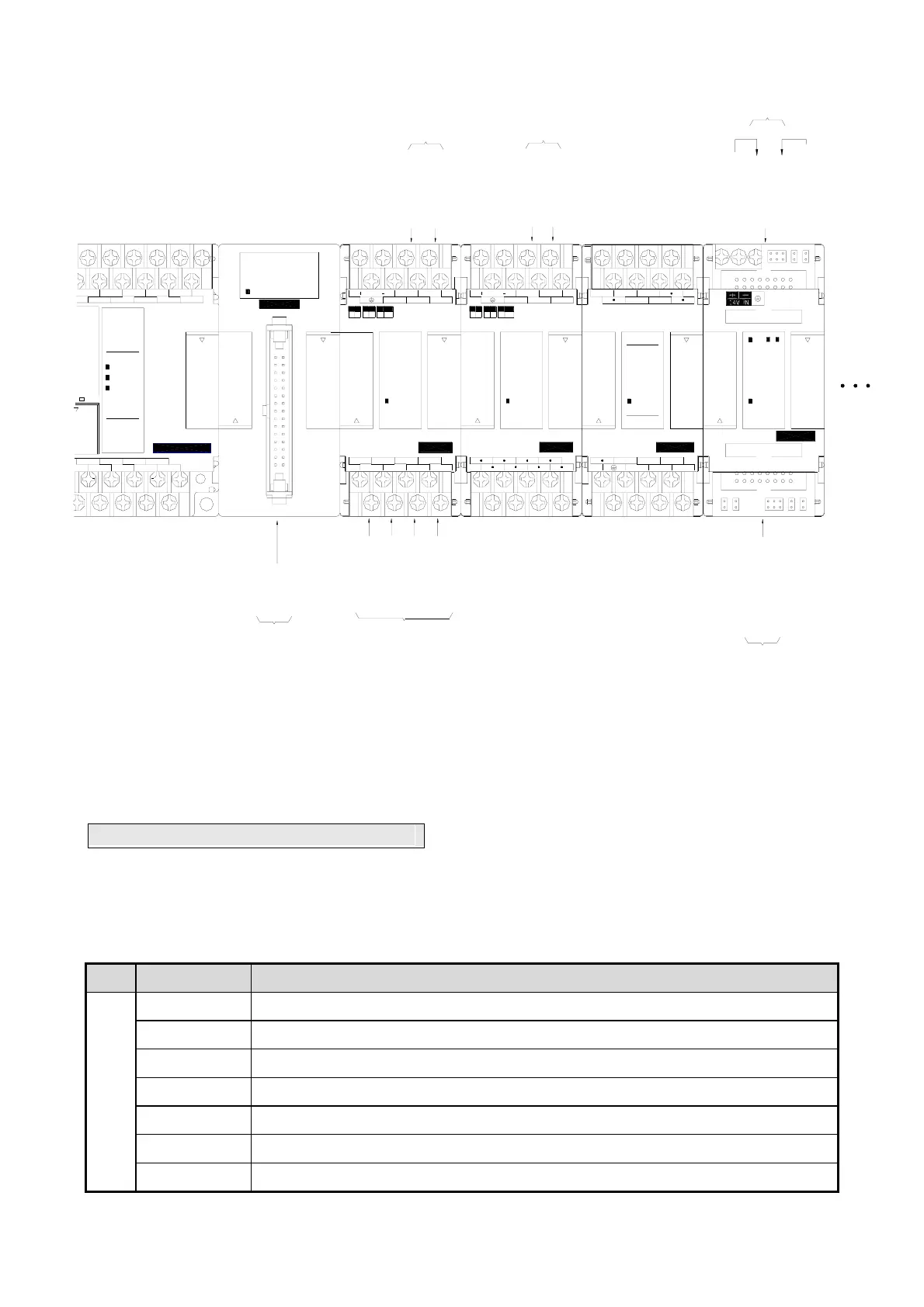
FBs-24MCR2-AC
FBs-32DGI
FBs-2DA
FBs-6AD FBs-8XYR
FBs-7SG2
During the startup stage, FBs-PLC will automatically detect the types and CH numbers of expansion units/modules.
While operation, the FBs-PLC will read the CH input values from the NI module and stores them into corresponding
IR(R3804 ~ R3903) and outputs OR values (R3904~R3967) to channels on the NO module. No pre-configuration or
setting by users is required.
3.2 Expansion of Communication Port
The main unit of FBs-PLC has one built-in communication port (port 0, with optional USB or RS232 interface).
Expansion of communication ports can be achieved by employing Communication Board (CB) or Communication
Module (CM). The available models of CB and CM for FBs are:
Model Number Specifications
Communication Board
(CB)
FBs-CB2
1 RS232 (port2) communication board
FBs-CB22
2 RS232 (port1 & port2) communication boards
FBs-CB5
1 RS485 (port2) communication board
FBs-CB55
2 RS485 (port1 & port2) communication boards
FBs-CB25 1 RS232 (port1) + 1 RS485 (port2) communication board
FBs-CBE 1 Ethernet communication board
FBs-CBCAN 1 CANopen® communication board