H1-1
Chapter 1 Introduction of FATEK FBS Series PLC
The FATEK FBS Series PLC is a new generation of micro PLC equipped with excellent functions comparable to medium
or large PLC, with up to five communication ports. The maximum I/O numbers are 256 points for Digital Input (DI) and Digital
Output (DO), 64 words for Numeric Input (NI) and Numeric Output (NO). The Main Units of FB
S are available in three types: MA
(Economy Type), MC (High-Performance Type), and MN (High-Speed NC Type). With the combination of I/O point ranges from
10 to 60, a total of 17 models are available. Fifteen DI/DO and 19 NI/NO models are available for Expansion Units/Modules.
With interface options in RS232, RS485, USB, Ethernet, CANopen, Zigbee and GSM, the communication peripherals are
available with 15 boards and modules.
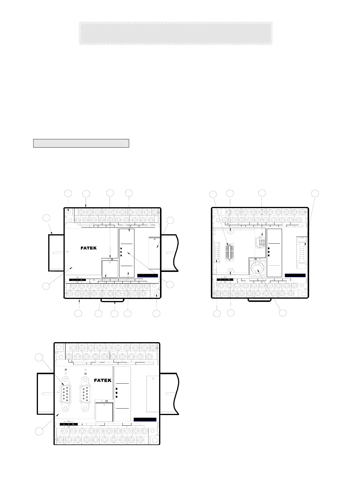
1.1 Appearance of Main Unit
All the Main Units of FBS-PLC have the same physical structure. The only difference is the case width. There are four different
case sizes, which are 60mm, 90mm, 130mm, and 175mm. The figure below will use the Main Unit case of the FBS-24MC as
an example for illustration:
( )
OUT Y
Y6Y1
AC100~240V
C0
Y0
Y4
Y2
C2 Y3
PORT0
Y5
C4 C6
0
4
8
2I
65
9
Y8
Y7 Y9
3
7
( )
IN X
X8
X0
PROGRAMMABLE
CONTROLLER
24V OUT
S/S
RXTX
RUN
ERR
I2 I3
POW
X4X2
X1 X3
0
8
4
2I
I0
9
65
X6
X5 X7
X12
3
I I
7
X10
X9
X11 X13
X10
3I20
Y2
AC100~240V
C0
Y1
Y0
C2
8
Y4
Y3 C4
Y5 Y6
C6 Y7
9
5647
X2
TX
24V OUT
S/S
X0
X1
IN X
( )
RX
ERR
OUT Y
( )
POW
RUN
0
X3 X5
X4
X7
X6
X9
X8
Y8
Y9
X12
X11 X13
3
1
4
11
6
12
9
16
15
18
20
19
15
10
17
3
5
2
8
7
( 未裝通訊板之正視圖 )
( 蓋板掀開之正視圖 )
98
45
I
I2 I3
I
II0
67
32
max.
400mA
IN
400mA
max.
IN
FBs-24MCR2-AC
FBs-24MCR2-AC
13
14
X9
Y7
PORT1
Y0
PORT2
AC100~240V
C0
24V OUT
RX
TX
RX
S/S
TX
RX
Y4
PORT0
C2
Y1
Y3
Y2
CONTROLLER
TX
6574
9
C4
Y5
8
C6
Y6
POW
ERR
I
RUN
0
( )
OUT Y
23
PROGRAMMABLE
X4X0
X1 X3
X2
I3
I
5
9
4
I2
8
X5
0
X6
76
IN X
( )
I0
I
I
X8
2
X7
3
Y9
Y8
X12X10
X11 X13
400mA
max.
IN
FBs-24MCR2-AC
【 Hardware】
○
1
35mm-width DIN RAIL
○
2
DIN RAIL tab
○
3
Hole for screw fixation (ψ4.5×2)
○
4
Terminals of 24VDC power input and digital input
(Pitch 7.62mm)
○
5
Terminals of main power input and digital output
(Pitch 7.62mm)
○
6
Standard cover plate (without communication
board)
○
7
Cover plate of built-in communication port (Port 0)
(Front view without Communication Board)
(Front view with cover plate removed)
(Front view with CB-22 Board installed)