Basic Function Instruction
6 - 21
FUN 7 D
UDCTR
UP/DOWN COUNTER
(16-bit or 32-bit up and down 2-phase Counter)
FUN 7 D
UDCTR
Symbol
Operand
CV :
CKClock
CUP
Ladder symbol
U/D
CLR
Up/Down count
Clear counter
7D.UDCTR
PV :
Count-UP (FO0)
CV: The number of the Up/Down Counter
PV: Preset value of the counter or it's
register number
WX WY WM WS TMR CTR HR IR OR SR ROR DR K
Range
Ope-
rand
WX0
∣
WX240
WY0
∣
WY240
WM0
∣
WM1896
WS0
∣
WS984
T0
∣
T255
C0
∣
C255
R0
∣
R3839
R3840
∣
R3903
R3904
∣
R3967
R3968
∣
R4167
R5000
∣
R8071
D0
∣
D4095
16/32-bit
+/− number
CV ○ ○ ○ ○ ○ ○ ○ ○* ○* ○
PV ○ ○ ○ ○ ○ ○ ○ ○ ○ ○ ○ ○ ○
Description
● When the clear control “CLR” is 1, the counter’s CV will be reset to 0 and the counter will not be able to
count.
● When the clear control “CLR” is 0, counting will then be allowed. The nature of the instruction is a P
instruction. Therefore, when the clock “CK↑” is 0→1 (rising edge), the CV will increased by 1 (if U/D=1) or
decreased by 1 (if U/D=0).
● When CV=PV, FO0(“Count-Up) will change to 1”. If there are more clocks input, the counter will continue
counting which cause CV≠PV. Then, FO0 will immediately change to 0. This means the “Count-Up” signal
will only be equal to 1 if CV=PV, or else it will be equal to 0 (Care should be taken to this difference from
the “Count-Up” signal of the general counter).
● The upper limit of up count value is 32767 (16-bit) or 2147483647 (32-bit). After the upper limit is reached,
if another up count clock is received, the counting value will become –32768 or -2147483648 (the lower
limit of down count).
● The lower limit of down count value is -32767 (16-bit) or -2147483647 (32-bit). After the lower limit is
reached, if another down count clock is received, the counting value will become 32768 or 2147483648
(the upper limit of up count).
● If U/D is fixed as 1, the instruction will become a single-phase up count counter. If U/D is fixed as 0, the
instruction will become a single-phase down count counter.
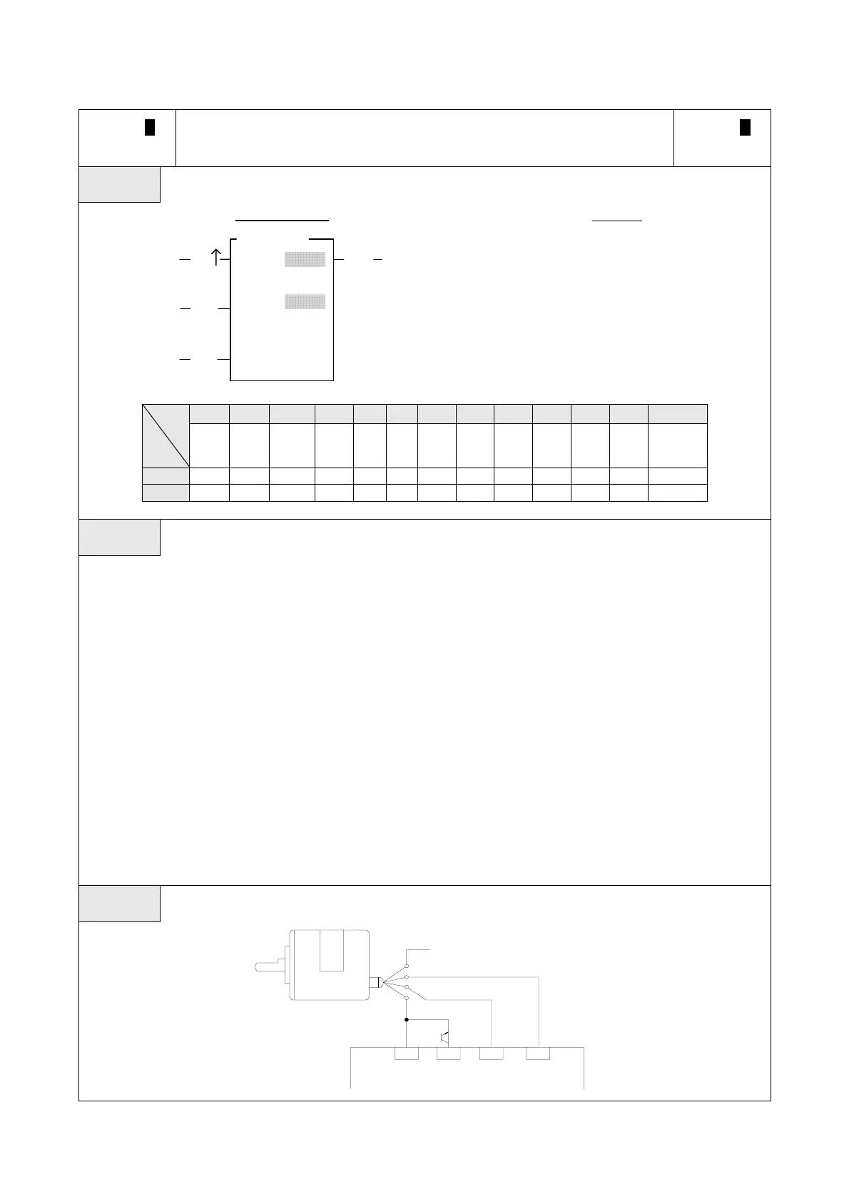
Example The diagram below is an application example of UDCTR instruction being applied to an encoder.
PLC
2-phase encoder
Black
Red (POWER + 24VDC)
Green (B phase)
White (A phase)
C
X16
X17
X18
SW