Advanced Function Instruction
7-59
FUN 78 D
DSW
DIGITAL SWITCH INPUT
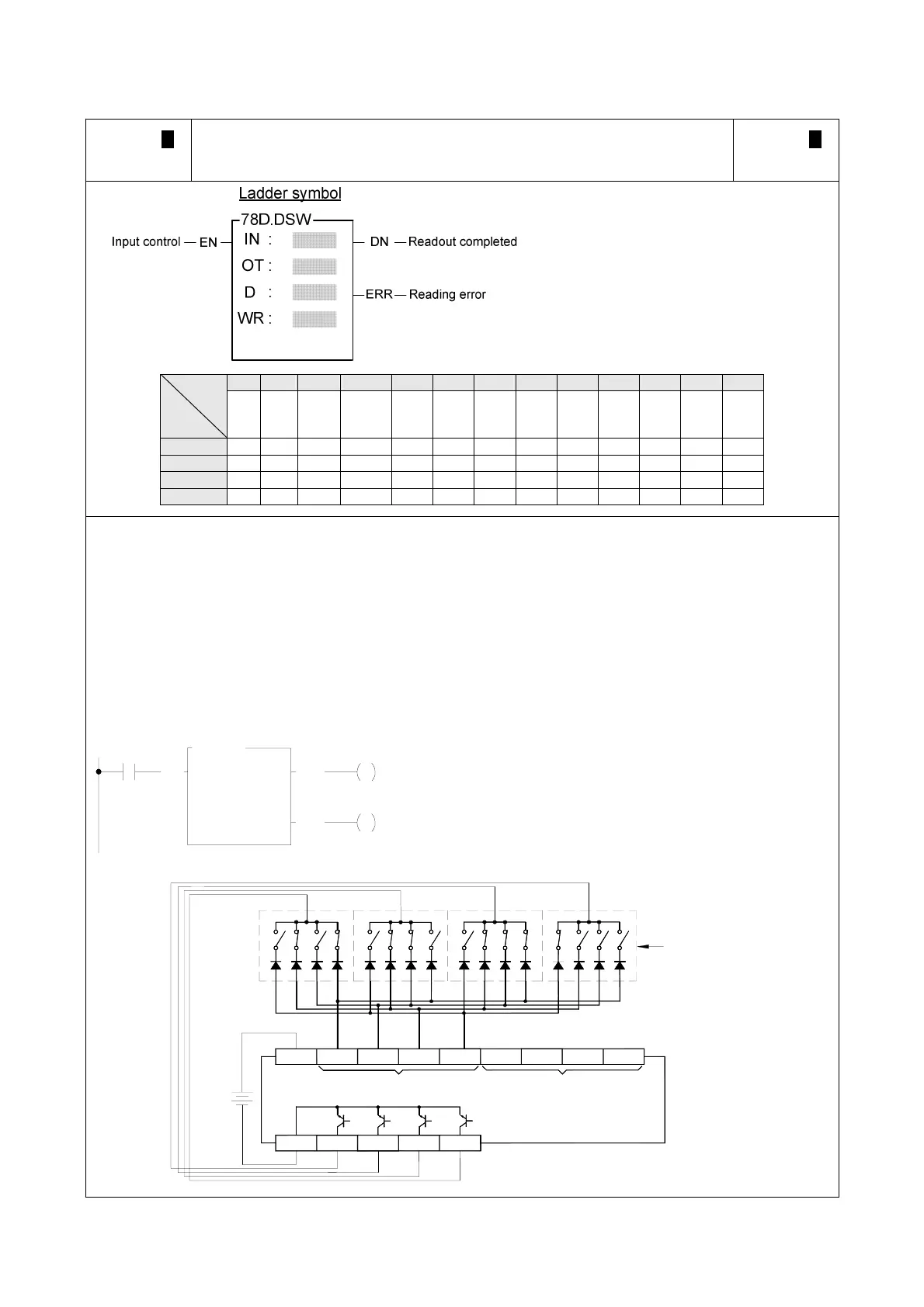
FUN 78 D
DSW
IN : Starting of input for thumb wheel switch
OT : Starting of output for multiplexing scan
(4 points)
D : Register to store readout value
WR: Working register, it can't repeat in use
(
WR & WR+1 for 16-bit operation;
WR, WR+1 & WR+2 for 32-bit operation)
D may combine with V、Z、P0~P9 to serve
indirect addressing application
X Y WY WM WS TMR CTR HR OR SR ROR DR XR
Range
Ope-
rand
X0
∣
X240
Y0
∣
Y240
WY0
∣
WY240
WM0
∣
WM1896
WS0
∣
WS984
T0
∣
T255
C0
∣
C255
R0
∣
R3839
R3904
∣
R3967
R3968
∣
R4167
R5000
∣
R8071
D0
∣
D4095
V、Z
P0~P9
IN ○
OT ○
D ○ ○ ○ ○ ○ ○ ○ ○* ○* ○ ○
WR ○ ○* ○
z When input control "EN" = 1, this instruction will readout one digit data from the 4 input points starting from
IN (IN0~IN3). It takes 4 scans to read out a group of 4-digit BCD values (0000~9999) and store them into D
register. With a 32-bit operand, each scan can get 2 digits of data by reading the additional digit from
IN4-IN7 and store it in the D+1 register. Each bit of OT0~OT3 will sequentially set to 1 and get the digit data
respectively into 10
0
(ones), 10
1
(tens), 10
2
(hundreds), and 10
3
(thousands). As long as EN is 1, PLC will
scan and read out in continuous cycles. When each complete cycle is finished (i.e. the 4 digit readout of
10
0
~10
3
is completed), the readout completed flag "DN" is set to 1. However, it is only kept for one scan. If
any digital readout value is not within the range of 0~9 (BCD), then reading error "ERR" will be set to 1 and
the value of that group of digits will be set to 0000.
z The output points must be transistor outputs.
X10
EN
IN : X0
M10
OT :
Y0
R0
D :
D0WR :
M11
DN
ERR
78.DSW
˙In this example, when X10 is 1, then the numeric value of the
thumb wheel switch (5678 in this example) will be read out
and stored into the R0 register.
˙The bits (8,4,2,1) with same digit should be connect together
and series with a diode (as shown in diagram below).
˙With 32-bit operand a set of similar thumb wheel switch may
be added to X4~X7 (Y0~Y3 are shared with another group).
8
BCD thumb
wheel swith
first group input
Y1Y0
C
Y2 Y3
X1
X0
S/S
1
24 1
4
X2
2
X3
8
second group input
(only effective in
32-bit operand)
PLC
X4 X5 X6 X7
3
(5)
10
2
(6)
10
10
1
(7) (8)
10
0
24V
1248
12481248
-
+