Advanced Function Instruction
7-61
FUN 79 D
7SGDL
7-SEGMENT OUTPUT WITH LATCH
FUN 79 D
7SGDL
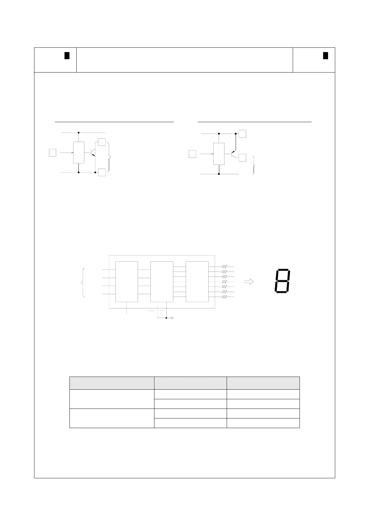
z FACON PLC's transistor output has both a negative logic transistor output (NPN transistor - when the output
status is ON, the terminal voltage of the transistor output is low), and a positive logic transistor output (PNP -
when the output status is ON, the terminal voltage of the transistor output is high). Their structure is as follows:
FBs-PLC negative logic output (NPN transistor)
FBs-PLC positive logic output (PNP transistor)
+24V
0V
Yn
Yn
C
+24V
When Yn is
"ON", this output
voltage is low
+24V
0V
Yn
Yn
C
+24V
0V
When Yn is "ON",
Yn's terminal
voltage is high
z The data inputs (8,4,2,1) and latch signals of the 7-segment displays on the shelf for positive and negative logic
are all available. For example, for numerical value "8", the positive logic input should be 1000, and the negative
logic input 0111. Similarly, when the latch signal is 0, the positive logic latch permits the display numerical values
to enter through the latch (i.e. be loaded). When the latch signal is 1, the numerical values in the latch are
latched (maintained), and with negative logic they are not. The following diagram of a CD-4511 7-segment
display IC is an example of a positive logic numerical value input with latch.
4bit
latch
BCD to
7-segment
LED
Drive
CD4511
(1)A
(2)B
(4)C
(8)D
(10 )
LE
Latch sing 1
LT
BI
VCC
R
a
b
c
d
e
f
g
Numberical value input
n
a
g
d
f
e
b
c
z Because the PLC output and the 7-segment display input polarity can be positive and negative logic. Therefore,
the polarities between output and input must be coordinated to get the correct result. This instruction uses N to
specify the polarity relation between the PLC transistor output, and the 7-segment display. The table below
shows all the possibility.
Numerical value input (8~1) Latch signal (10
0
-10
3
) Value of N
Same 0
Same
Different 1
Same 2
Different
Different 3
z In the diagram above, CD4511 is used as an example. If use NPN output, the data input polarity is different to
PLC, and its latch input polarity is the same as PLC, so N value should chosen as 2.