Advanced Function Instruction
7-116
FUN140
HSPSO
HIGH SPEED PULSE OUTPUT INSTRUCTION
(Brief description on function)
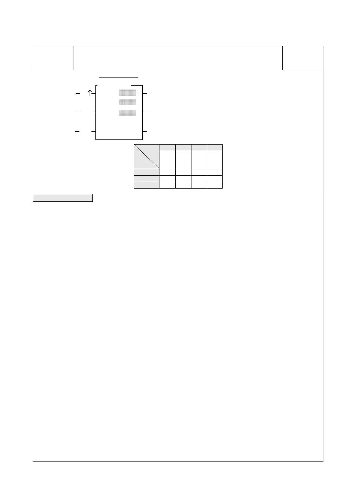
FUN140
HSPSO
Ps :
EN
Execution control
Ladder symbol
140.HSPSO
ACT
ERRPause INC
Abort
ABT
SR :
WR :
DN
Ps : The Pulse Output (0~3) selection
0:Y0 & Y1
1:Y2 & Y3
2:Y4 & Y5
3:Y6 & Y7
SR : Positioning program starting register.
WR : Starting working register of instruction operation,
total 7 registers, can not used in any other part of
program.
HR DR ROR K
Range
Ope-
rand
R0
∣
R3839
D0
∣
D4095
R5000
∣
R8071
2
∣
256
Ps 0~3
SR ○ ○ ○
WR ○ ○ ○*
Command descriptions
z The NC positioning program of HSPSO (FUN140) instruction is a program written and edited with text. The
executing unit of program is divided by step (which includes output frequency, traveling distance, and
transferring conditions). For one FUN140 instruction, can program 250 steps of positioning points at the most.
Each step of positioning program requires 9 registers. For detailed application, please refer to chapter 13 “the
NC positioning control of FBs-PLC”.
z The benefits of storing the positioning program in the register is that, while in application which use the MMI
(man machine interface) as the operation console can save the positioning programs to MMI. Whenever the
change of the positioning programs is requested, the download of positioning program can be simply done by
a series of write register commands.
z The NC positioning of this instruction doesn’t provide the linear interpolation function.
z When execution control “EN”=1, if Ps0~3 is not controlled by other FUN140 instruction (the status of
Ps0=M1992, Ps1=M1993, Ps2=M1994, and Ps3=M1995 is ON respectively), it will start to execute from the
next step of positioning point (when goes to the last step, it will be restarted from the first step); if Ps0~3 is
controlled by other FUN140 instruction (the status of Ps0=M1992, Ps1=M1993, Ps2=M1994, and
Ps3=M1995 are OFF), this instruction will wait and acquires the control right of output point immediately right
after other FUN140 release the output.
z When execution control input “EN” =0, it stops the pulse output immediately.
z
When output pause “PAU” =1 and execution control was 1, it will pause the pulse output. When output
pause “PAU” =0 and execution control is still 1, it will continue the unfinished pulse output.
z
When output abort “ABT”=1, it will halt and stop pulse output immediately. (When the execution control
input “EN” becomes 1 next time, it will restart from the first step of positioning point to execute.)
z
While send the output pulse, the output indication “ACT” is ON.
z
When there is an execution error, the output indication “ERR” will be ON. (The error code is stored in the
error code register.)
z
When the execution of each step of positioning program is completed, the output indication “DN” will be ON.
*** The working mode of Pulse Output must be configured (without setting, Y0~Y7 will be treated as normal
output) to any one of following modes, before the HSPSO instruction can be worked.
U/D Mode: Y0 (Y2, Y4, Y6), as up pulse.
Y1 (Y3, Y5, Y7), as down pulse.
K/R Mode: Y0 (Y2, Y4, Y6), as the pulse out..
Y1 (Y3, Y5, Y7), as the direction.
A/B Mode: Y0 (Y2, Y4, Y6), as A phase pulse.
Y1 (Y3, Y5, Y7), as B phase pulse.
hThe output polarity for Pulse Output can select to be Normally ON or Normally OFF.
hThe working mode of Pulse Output can be configured by WINPROLADDER in “Output Setup” setting page.
 Loading...
