5-2
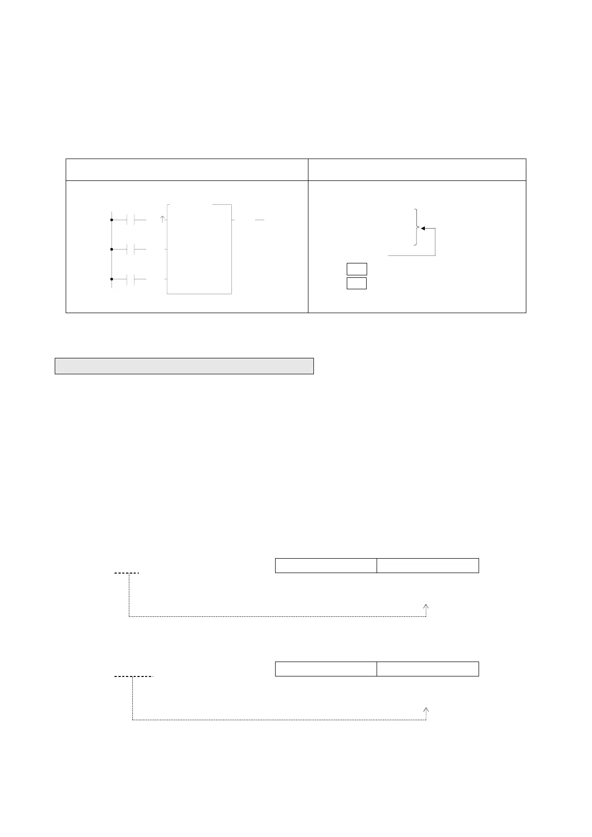
All input controls of the function instructions should be connected by the corresponding elements, otherwise a syntax
error will occur. As shown in example 3 below, the function instruction FUN7 has three inputs and three elements before
FUN7. ORG X0, LD X1 and LD X2 corresponds to the first input CK↑, second input U/D and third input CLR.
Example 3:
Ladder Diagram FP-07 Mnemonic code
X0
X2
7.UDCTR
CV :
PV :
CK
U/D
CLR
R
0
10
CUP
X1
ORG X 0
LD
X 1
LD
X 2
FUN
7
CV :
R 0
PV : 10
FUN7 need three
elements because
it has three inputs
5.1.2 Instruction Number and Derivative Instructions
As mentioned before, except for the nine instructions that can be entered using the dedicated keys on the keyboard, other
function instructions must be entered using the "instruction number”. Follow the instruction number there are postfixes D,
P, DP can be added which can derive three additional function instructions.
D: Indicates a Double Word (32-bit). The 16-bit word is the basic unit of the registers in FBs-PLC. The data length of R, T
and C (except C200~C255) registers are 16-bit. If a register with 32-bit data length is required, then it is necessary to
combine two consecutive 16-bit registers together such as R1-R0, R3-R2 etc. and those registers are represented by
prefix a D letter before register name such as DR0 represents R1-R0 and DR2 represents R3-R2. If you enter DR0 or
DWY8 in the monitor mode of FP-07, then a 32-bit long value (R1-R0 or WY24-WY8) will be displayed.
B31 B16 B15 B0
DR0 =R1−R0 R1 R0
↑ ↑
High Word register Low Word register
B31 B16 B15 B0
DWY8 =WY24−WY8 WY24 WY8
=Y39~Y8 ↑ ↑
High Word register Low Word register