H7-7
電 子
電 路
PLC
繼電器
R
湧浪電流使接點熔化黏住
Load
R
V
I s
I r
C
VDD
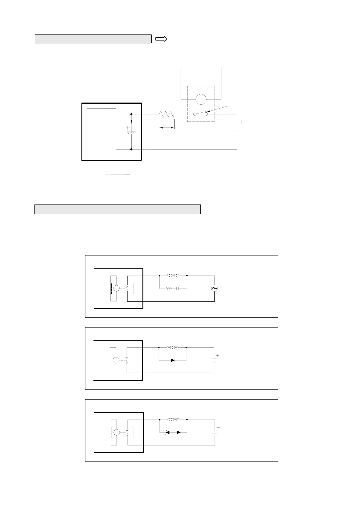
A. Suppression of Surge Current 以 Connect a small resistor R in series to lower the surge current,
but note that too large R will affect the driving capability or cause too much voltage drop.
B. Suppression of Counter-Electromotive Force
For the inductive load, whether in AC or DC power, suppression devices must be connected in parallel to both its
ends to protect the relay contacts and lower noise interference. The schematic diagrams for AC and DC powers are
shown below, respectively:
R : 100 ~ 120Ω
C : 0.1 ~ 0.24uF
PLC Relay output
R
Inductive load
R
C
Scheme of AC power load
R
D : 1N4001 diode or
equivalent device
PLC Relay output
Inductive load
VDC
D
Suppress by a diode in DC power load (for low power)
R
PLC Relay output
Inductive load
VDC
ZD
D
D : 1N4001 diode or
equivalent device
ZD : 9V Zener, 5W
Suppress by a diode + Zener in DC power load (for high power and frequent ON/OFF)
VDD
R≧ (note power dissipation P=Is
2
R and voltage drop V=IsR)
Ir max
Ir max of relay in FBS-PLC =5A
Surge current welds contacts
Load
Electronic
Circuits
PLC output
relay
R:100~120Ω
C:0.1~0.24uF
Is
Ir