ENGLISH
7. VARIOUS CONNECTIONS
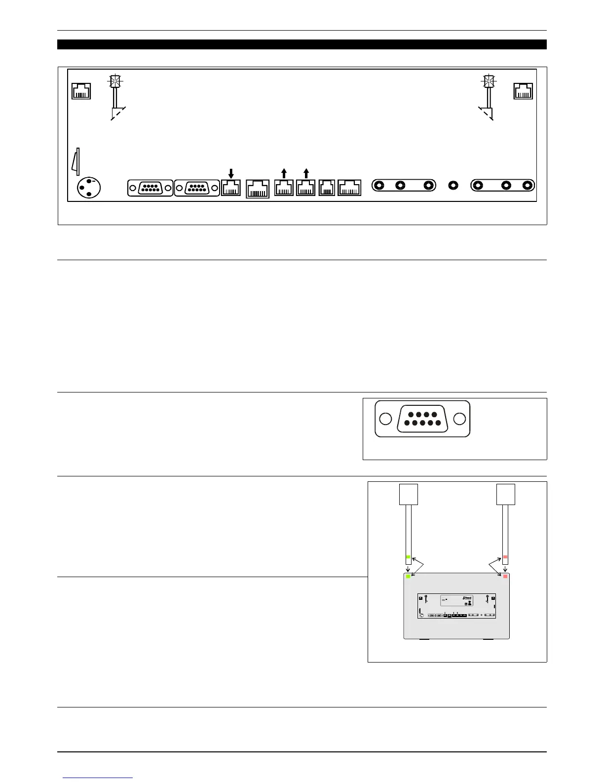
All connections are located at the back of the FA-07 and indicated by their relative labels (see Fig. 16).
7.1 SERIAL DATA ports and REPEATER function
The FA-07 is equipped with 3 SERIAL DATA ports: 2 OUTPUT ports and 1 INPUT port. All ports are opto-isolated to protect
fencers from dangerous high voltages.
By using regular telephone cables, the ports can be easily connected to other FA-07 apparatuses or to other Favero
Electronic Design devices, with a distance of up to 100m. The two cables provided are 15m and 2.5m in length. Several FA-
07s can be connected, in a cascade configuration, from the SERIAL DATA OUTPUT port of one apparatus to the INPUT port
of another. The first works as a piste apparatus and the others as repeaters.
On the graphic display panel of the repeater apparatuses, the word “REPEATER” will appear. Via the [F3] key, either the word
“FRONT VIEW” or the word “BACK VIEW” can be selected. By selecting the word “BACK VIEW”, a complete inversion of the
displayed information results, such that two FA-07s positioned back to back will display, at 360°, all information and lights on
the same side (i.e., on the side corresponding to the fencer’s position).
If necessary, each OUTPUT port can be redoubled by using the special doubler (Art. 880).
7.2 RS-422 Ports
The FA-07 comes provided with two RS-422 ports for sending all data to
external data gathering, visualization, and Video-refereeing systems, and for
TV-Superimpositions. All ports are opto-isolated to protect fencers from
dangerous high voltages. The connections of signals are shown in Fig. 17.
Each OUTPUT port can drive 8 INPUT ports.
The communications protocol is provided upon request.
7.3 Ethernet Port
The FA-07 comes with a 10Base-T/100Base-Tx Ethernet port. This port allows
the FA-07 to be connected:
A) directly to a PC for updating software, as described in chapter 8,
B) to a LAN in order to manage the entire competition via the central
system, as described in chapter 6.
The Ethernet port has a 1500V isolation to protect fencers from any
dangerous high voltages.
7.4 Tower-Lights Connection
The pair of Tower-Lights is an optional accessory and is not provided with the
FA-07. Installation is simple and does not require tools:
1. Identify the colour of the two Tower-Lights (red and green), indicated by a
label located at the lower end of the support pole of each tower. See Fig.
18.
2. Insert the Tower-Towers poles into the corresponding slits located at the top
corners of the FA-07. Make sure the colour of the pole and the slit
correspond.
3. Each Tower-Light comes with a cable and connector: insert the connector in
the proper “Tower Lights” socket.
7.5 “STM-Wireless” connection
On the back of the FA-07 there is a “STM Wireless device” connector for connecting to the relative wireless system. When this
connection is made, the FA-07 automatically displays the words “STM-Wireless” and is prepared to work in synch with the
“STM-wireless” system.
FAVERO ELECTRONICS SRL
Page 14 / 16
940-M06-EN FA-07 Manual