77X INSTALLATION & OPERATION MANUAL
771/772/773/774 MODELS
65
P
S
SS
FLOW
T
SCROLL
COMPRESSOR
PRESSURE
EXPANSION
VALVE & SOLENOID
DEFROST
VALVE &SOLENOID
EVAPORATOR
EVAPORATOR
EVAPORATOR
TEMPERATURE
HEAT
EXCHANGER
FILTER
DRIER
PRESSURE
LIQUID RECEIVER
P
CONDENSER
NOTE: DIAGRAM
SHOWN FOR 773
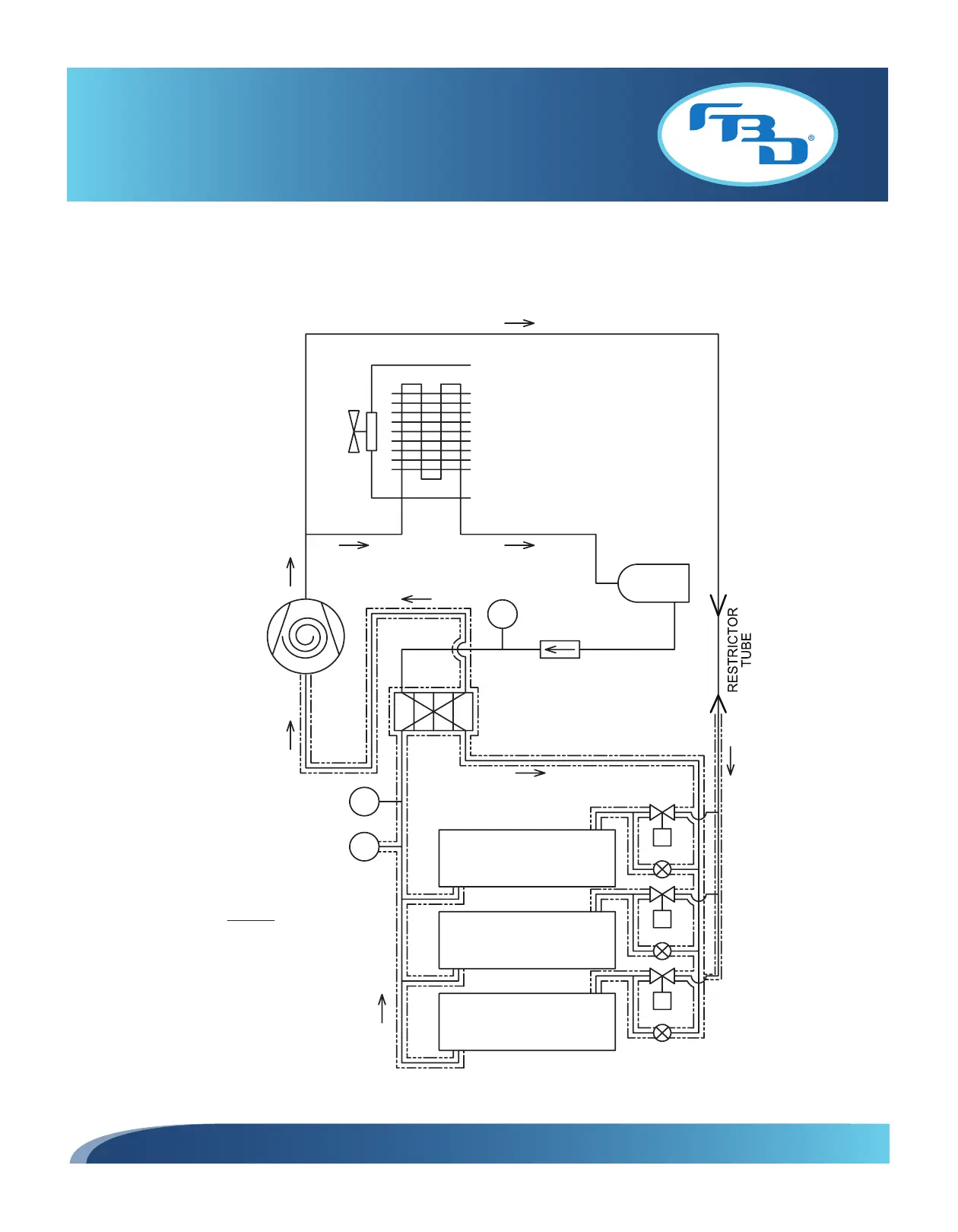
Figure 11.15 Refrigeration Schematic for 772 and 773 Standard Air-Cooled Dispensers
11.7 Refrigeration Schematic Diagrams (Air-Cooled Dispensers)
Figure 11.15 shows the refrigeration schematic for the standard 773 air-cooled dispenser and is representative of the
standard 772 with the exception of the number of barrels. Figure 11.16 shows the diagram for the standard 774 air-
cooled dispenser.