FS10 Series 06EN003394 Rev. K
Fluid Components International LLC iii
Table of Contents
TECHNICAL SPECIFICATIONS .....................................................................................................................................................................1
1 INSTRUMENT DESCRIPTION AND IDENTIFICATION .........................................................................................................................2
2 INSTRUMENT INSTALLATION ................................................................................................................................................................2
Special Conditions for Safe Use.......................................................................................................................................................................................2
Remote Flow Element Installation Into Zone 1, Division 1 Areas ...................................................................................................................................2
Mounting Orientation .......................................................................................................................................................................................................3
3 INSTRUMENT WIRING ............................................................................................................................................................................ .4
Recommended Minimum Wire Gauge ............................................................................................................................................................................4
Grounding .........................................................................................................................................................................................................................4
Input Power, 24 VDC ......................................................................................................................................................................................................... 4
FS10 Output Modes .......................................................................................................................................................................................................... 8
Switching Inductive Loads................................................................................................................................................................................................8
FS10 Outline Installation Drawing ...................................................................................................................................................................................9
FS10 1/4-Inch Tube Tee Assy With 1/8” Tube Adapters And Injection Tubes ............................................................................................................... 10
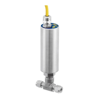
FS10 Flow Element Options............................................................................................................................................................................................11
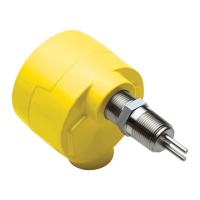
FS10 Remote Enclosure and Connection Options ..........................................................................................................................................................12
FS10i Top Assembly ........................................................................................................................................................................................................13
Configuration Overview ............................................................................................................................................................................................... 13
Sensor Subassembly ...................................................................................................................................................................................................14
Dimensional Outlines .....................................................................................................................................................................................................15
Installation Dimensions, FS10 Remote Panel Mounting Ring Kit (025719-01)..............................................................................................................17
Installation Dimensions, FS10 Remote Mounting Bracket (025442-01) ........................................................................................................................18
Installation Details, FS10 Silicone Boot and UV Filter ................................................................................................................................................... 19
4 POWER UP, FUNCTIONAL VERIFICATION AND ADJUSTMENT ......................................................................................................21
5 SET-UP AND OPERATION ......................................................................................................................................................................21
FS10 Function Overview .................................................................................................................................................................................................21
FS10 Field Quick Setup Procedure..................................................................................................................................................................................22
Quick Setup Mode Summary .......................................................................................................................................................................................... 23
FS10 Button Controls – Alternate Setup Method ..........................................................................................................................................................25
Normal Set-Up and Operation Using the Button Interface ............................................................................................................................................26
Flow Switch Operation ...................................................................................................................................................................................................26
Minimum Flow Setting (Function 6) ............................................................................................................................................................................26
Maximum Flow Setting (Function 7) ...........................................................................................................................................................................26
Switch Point Adjust (Function 1 or 2) .......................................................................................................................................................................... 26
Additional Switch Settings.............................................................................................................................................................................................27
Fail-safe Position (Function 3) .....................................................................................................................................................................................27
Hysteresis (Function 8 and 9) ......................................................................................................................................................................................27
Time Delay (Function 10 or 11) .................................................................................................................................................................................... 27
Alarm Simulation (Function 12) ................................................................................................................................................................................... 27
Filter Setting (Function 14) ..........................................................................................................................................................................................27
FS10 Recommended Point Level Interface Setup Procedure .........................................................................................................................................28