5
2. Hardware Part
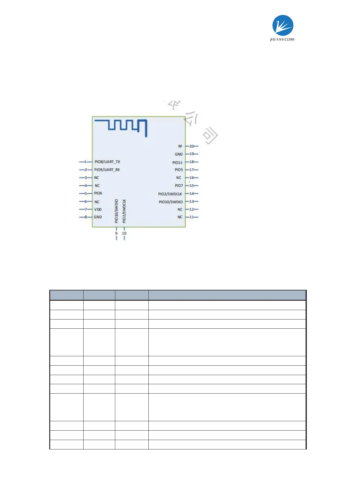
2.2 PIN diagram
2.3 PIN definition description
PIN Name
Pin Type PIN Description
NC Not recommended to connect
UART_TX
1 I/O UART TX
UART_RX
2 I/O UART RX
TRAN 5 I
When the Bluetooth connection is established and the pin
function is enabled, the high level is the command mode,
and the low level is the transparent transmission mode
VDD 7 Power
GND 8,19 Power
SWDIO 9 I/O
SWDCLK
10 I/O
DISC 15 I
When the Bluetooth connection is established and the pin
function is enabled, the falling edge triggers
the disconnection of the Bluetooth connection.
LED 17 O Module work status
STATUS
18 O Bluetooth connection status indicator
RF 20 RF Use when using an external antenna