MSD
TM
Series
© Copyright 2018 Fluid Equipment Development Company | www.fedco-usa.com
- 37 -
Pump Assembly Continued
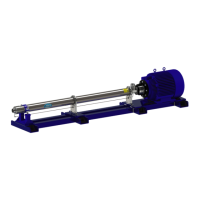
Figure 63 - Aligning Pump Shaft Keyway
6. Rotate both shafts until the pump shaft
key and the exible coupling keyway are
aligned.
APPLY SYSTEM COMPLIANT
ANTI-SEIZE COMPOUND
Figure 62 - Pump Shaft Key Installation
5. Apply system compliant anti-seize com-
pound in the pump shaft keyway and install
pump shaft key
NOTES: The rounded end of the pump shaft
key must be placed in the rounded end of the
keyway.
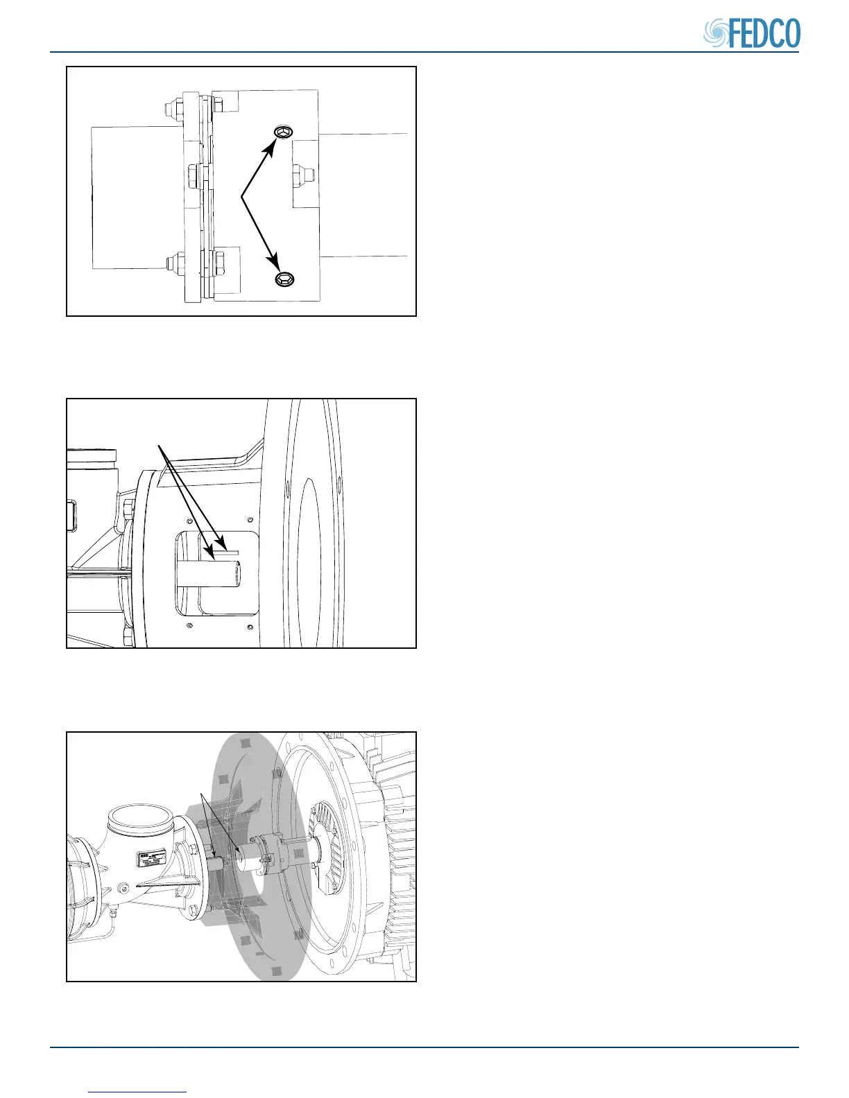
Figure 61 - Flexible Coupling Set Screw
Location
4. Install the exible couple set screws and
tighten to torque specs specied in the Fas-
tener Torque Specications section of this
manual.
NOTES: Set screws are only on the motor side
of the exible coupling. No set screws should
be installed on the pump shaft side of the cou-
pling.