MSD
TM
Series
© Copyright 2018 Fluid Equipment Development Company | www.fedco-usa.com
- 44 -
Pump Assembly Continued
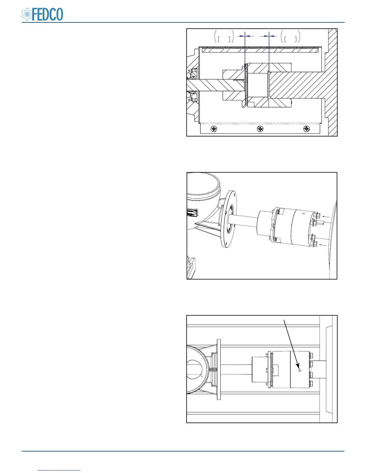
.125
3.18
.125
3.18
Figure 84 - Installing Dropout Coupling Set
Screw
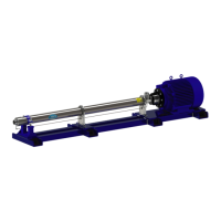
Figure 83 - Joining Coupling Hubs
Figure 82 - Dropout Coupling Cross Section
14. Install the dropout coupling set screw and
tighten to torque specs found in the Fas-
tener Torque Specications section of this
manual.
NOTES: Set screws are only on the motor side
of the dropout coupling. NO set screws should
be installed on the pump shaft side of the cou-
pling.
13. Join the motor hub with the dropout hub us-
ing hardware removed in step 2.
NOTES: If indicating pump using the Reverse
Indicator or a Laser Alignment Tool Method,
tighten dropout coupling set screw and initiate
alignment process. Upon completion, remove
coupling and alignment bushing as described
in step 1. Re-install dropout coupling and pro-
ceed with next step.
NOTES: Remove alignment bushing before
operation.
NOTES: Cross section for reference only.