601 Old Airport Road • Bristol, VA 24201 Phone (276) 669-4084 • FAX (276) 669-1869 • www.federalpacific.com • ISO9001:2015
SECTION IB-2A-210
INSTALLATION & OPERATION INSTRUCTIONS
TYPE PSE PAD-MOUNTED SWITCHGEAR
NOVEMBER 2017, REV 4.2
PAGE 5
Customer Cable Connections
1. Make up the primary cable connections per user’s standard URD
operating procedures, cable manufacturer instructions, and elbow
terminator manufacturer instructions.
Installation
Each unit is shipped with this instruction bulletin, which is located
inside the switch compartment door. These instructions should be
reviewed prior to placing unit on pad.
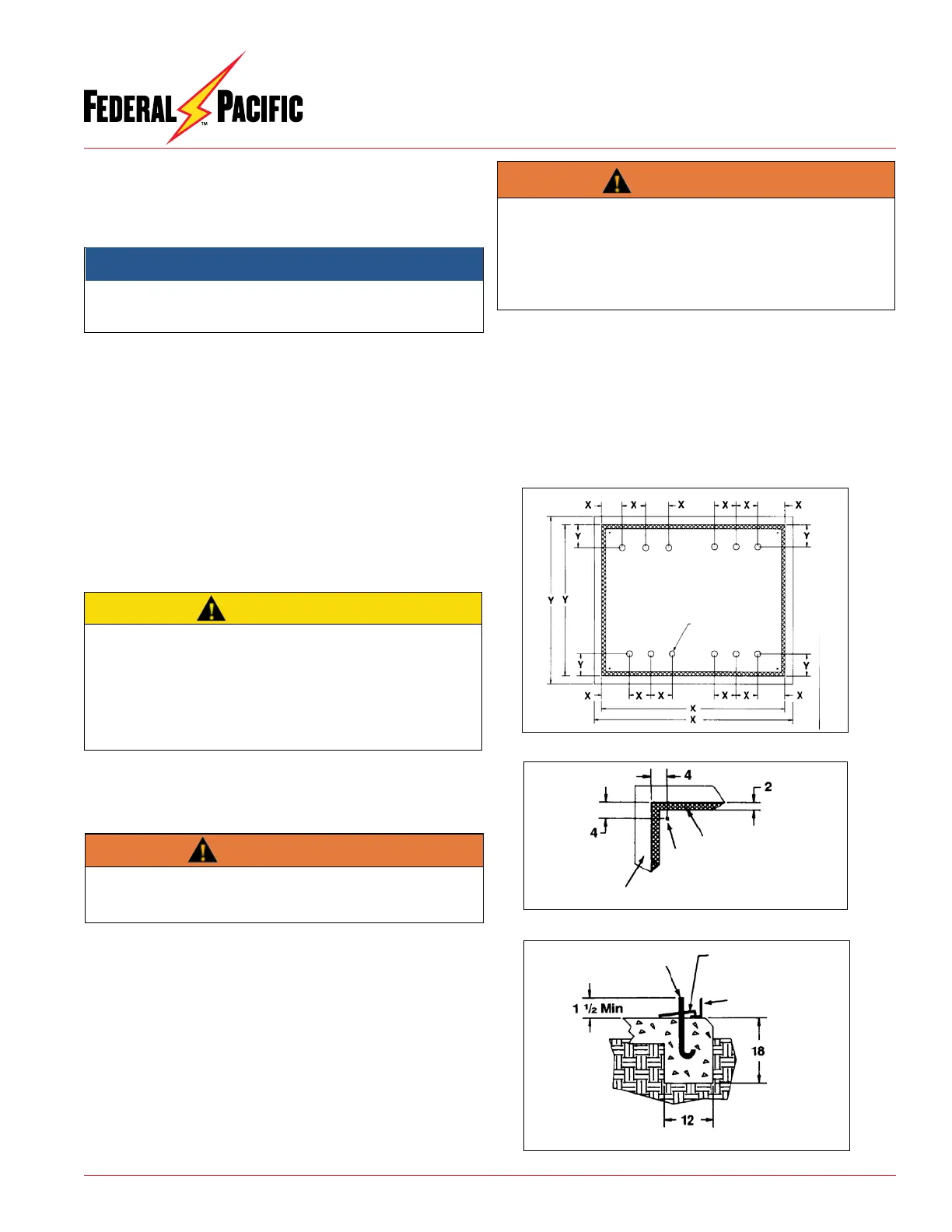
Placement of Unit
Remove unit from shipping pallet per handling procedures on Page
2 (see Figure 3). When unit has been correctly oriented and placed
on pad (see Figure 7), verify that unit is level and shim if necessary
between unit base and pad. Secure unit to pad using four (4) tie-down
clips as furnished (see Figures 8 and 9). Check compartment door
operation for any binding due to enclosure distortion and re-shim
if necessary. A recessed grouting should then be applied between
unit base and pad to prevent entry of foreign objects and moisture.
Figure 7. Typical Pad Layout
PSE-X
Recommended Pad Layout
Approximate Cable
Locations
Figure 8. Typical Anchor Bolt Location
Base of Cabinet
Customers Pad
Corner Detail
Anchor Bolt
Figure 9. Bolting Units to Pad
Cabinet
5/8-11 Anchor
Bolts (by others)
4 Tie Down
Plates Provided w/Unit
Recommended Pad Section
Before energizing the switchgear, remove all yellow and red
shipping caps on bushings and bushing wells, and replace
them with a suitable system of insulated separable connectors
(elbows), insulating protective covers, or plugs, as appropriate.
Failure to replace the shipping caps may result in flashover,
equipment damage, serious personal injury, or death.
WARNING
2. Connect the concentric neutral wires to the enclosure ground
pads inside enclosure to facilitate ground system conforming to
user’s grounding procedures.
NOTICE
Installer shall provide appropriate clear working space, as re-
quired by applicable codes and/or work practices, to allow instal-
lation, operation, inspection, and maintenance of the switchgear.
CAUTION
When terminating cables in dead-front switchgear, ensure that
each cable termination connector lays flat against the correspond-
ing flat copper contact surface of the associated bushing, prior
to making up the elbow, so that no additional strain is put on the
bushing. The connecting hardware and components of dead-break
T-body elbows are not to be used to pull the cable terminations
into alignment with the bushings.
3. Install fault indicators, if applicable.
4. Fuse Compartment Cable Positioning
a) Cable connections to the loadbreak fuse mounting terminals must
be fed through the cable guides, which are located under the
parking stands. This is required to permit the proper operation
of the pivoting fuse mountings.
b) Each cable guide may be rotated or temporarily removed to
facilitate cable installation, so long as it is returned to its original
orientation, under its corresponding parking stand, after the
cables are installed.
Switch Description
The Auto-jet
®
II switch provides a unique method of load interruption,
producing a laminated jet of air which extinguishes the arc.
Auto-jet
®
II switches have a heavy gauge steel, all welded base
frame that assures proper alignment and eliminates any problem
with switch-to-enclosure alignment. A quick-make, quick-break
stored energy mechanism with heavy duty, long life die springs
provides high speed opening and closing independent of the op-
erating handle speed.
WARNING
The maximum momentary rating of the switchgear must be
considered when selecting cable size for connecting switch-
gear to system ground. Refer to unit rating plate.