601 Old Airport Road • Bristol, VA 24201 Phone (276) 669-4084 • FAX (276) 669-1869 • www.federalpacific.com • ISO9001:2015
SECTION IB-2A-210
INSTALLATION & OPERATION INSTRUCTIONS
TYPE PSE PAD-MOUNTED SWITCHGEAR
NOVEMBER 2017, REV 4.2
PAGE 6
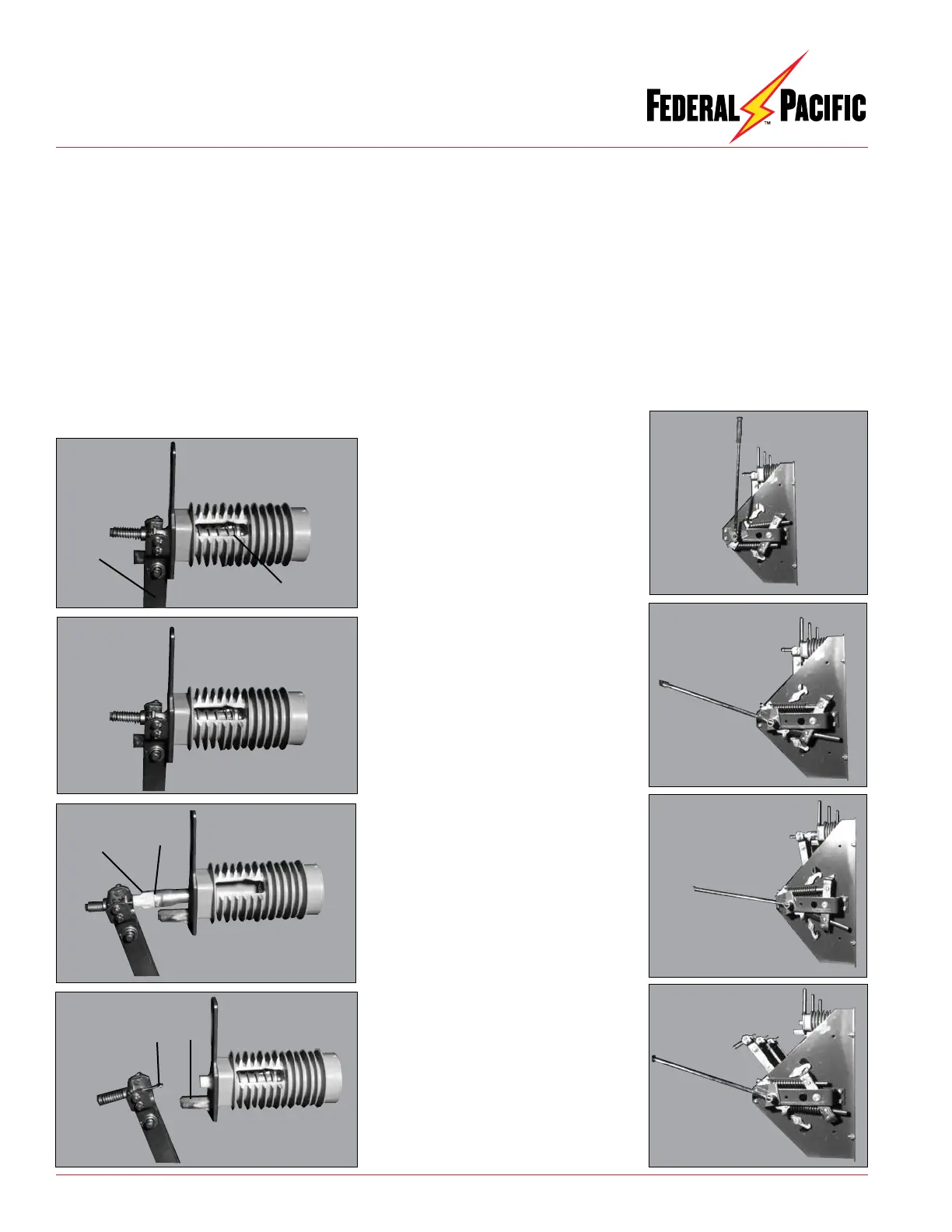
The operating sequence of the Auto-jet
®
interrupter is pictured
in the left-hand column in Figures 10(a) through 10(d) and the
corresponding positions of the switch and its mechanism are
pictured in the right-hand column. The Auto-jet
®
interrupter con-
sists of a piston (A) mounted in the cavity of the upper insulator.
The movable arcing probe (B) engages a tulip contact (C) inside
the piston. As the switch blade (D) is pulled open by the stored
energy mechanism, the blade separates from the main-contact
stab (E). The piston is pulled forward by means of the movable
arcing probe, which compresses a heavy gauge spring encircling
the piston and a spring encircling the arcing probe. At the end of
its travel, the piston is released from the arcing probe and, under
the action of the heavy spring, is rapidly pushed backward into
the cavity. This travel produces a jet of laminated compressed air
up through the center of the piston, which extinguishes the arc.
The spring encircling the movable arcing probe rapidly retracts
the probe and increases the speed of separation, which prevents
restrike. All of this action is in addition to the spring energy transmitted
to the switch blades by the quick-make quick-break mechanism
of the switch.
Switch Operating Sequence
Figure 10(d)
Switch open with latch
engaged to hold switch in
position.
Figure 10(c)
Main contacts parted, puffer
and arcing springs charged.
(Simulated condition for
illustrative purposes, actual
duration of event is approx.
1/2 cycle.)
Figure 10(b)
Switch closed with opening
spring charged by manual
operating handle.
Figure 10(a)
Switch closed with opening
spring relaxed.
Cutaway Views of Interrupter
Views of Switch
D
A
B
E
C
A