601 Old Airport Road • Bristol, VA 24201 Phone (276) 669-4084 • FAX (276) 669-1869 • www.federalpacific.com • ISO9001:2015
SECTION IB-2A-210
INSTALLATION & OPERATION INSTRUCTIONS
TYPE PSE PAD-MOUNTED SWITCHGEAR
NOVEMBER 2017, REV 4.2
PAGE 9
Fuse Description
The PSE pivoting fuse mounting provides a convenient means
to install fuses during initial energization as well as during fuse
replacement. The fuse mounting includes an interlocking latch that
prevents access to fuses unless the elbow connector is removed,
while also providing a convenient means to unlatch and lower the
fuse mounting.
The PSE fuse mountings include a heavy gauge formed channel
base with viewing windows to observe the blown fuse indicator.
A GPO-3 fiberglass barrier blocks access to the interior of the PSE
unit, precluding exposure to high voltage, while the fuse mounting
is lowered. When the fuse mounting is in the lowered position, the
fuse is completely de-energized and isolated from high voltage.
A locking bracket secures the fuse mounting to the door stile,
facilitating fuse removal.
Fuse Removal
1. Open appropriate fuse compartment door and secure with
the wind stop. See Figure 17.
2. Install the grappler tool on the universal head of the shotgun
clamp stick.
3. Using the shotgun clamp stick, install the feed-through standoff
bushing on the parking stand. See Figure 18.
4. If appropriate for operating circumstances of the system,
test the elbow to be moved for voltage. After verifying that
voltage is not present, use the shotgun clamp stick to remove
the elbow connector from the appropriate bushing well, fol-
lowing standard system operating procedures and the elbow
manufacturer’s instructions. Move the elbow connector onto
a standard feed-thru standoff bushing that is placed in the
parking stand. See Figures 19, 20, and 21.
5.
Install an insulating protective cover on the exposed 200-amp
bushing well insert. See Figure 22.
6 If appropriate for operating circumstances of the system,
test the remaining feed-through standoff bushing for voltage
and, after confirming that voltage is not present, then install
a grounding elbow on the remaining bushing.
7. The fuse-panel latch interlock prevents access to fuses un-
less the elbow connector is removed to allow release of the
interlock. Secure the shotgun clamp stick to the interlock
lever and raise the interlock. See Figures 23 and 24.
8. With the shotgun clamp stick still secured on the interlock
lever, pull on the fuse panel; lower it to a horizontal position
and release the shotgun clamp stick. See Figure 25.
Figure 18. Feed through standoff bushing installed on
parking stand.
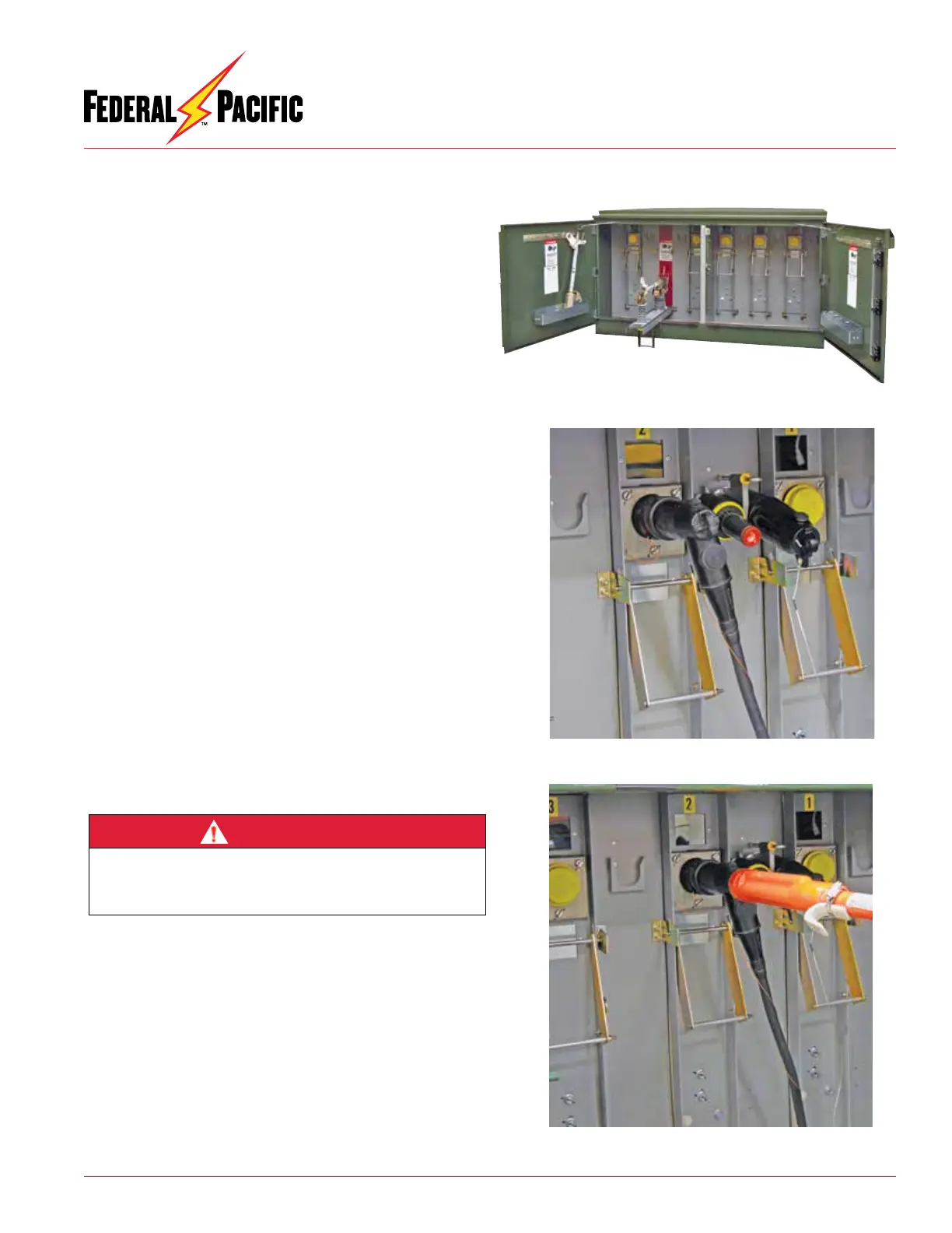
Figure 19. Shotgun clamp stick secured to elbow for
removal/connection.
Figure 17. Fuse compartments with doors secured open.
DANGER
Before installing grounding elbows, test for voltage. Failure to
properly test for voltage to establish that circuit is de-energized
before installing grounding elbow may result in equipment dam-
age, personal injury or death.