601 Old Airport Road • Bristol, VA 24201 Phone (276) 669-4084 • FAX (276) 669-1869 • www.federalpacific.com • ISO9001:2015
SECTION IB-2A-210
INSTALLATION & OPERATION INSTRUCTIONS
TYPE PSE PAD-MOUNTED SWITCHGEAR
NOVEMBER 2017, REV 4.2
PAGE 8
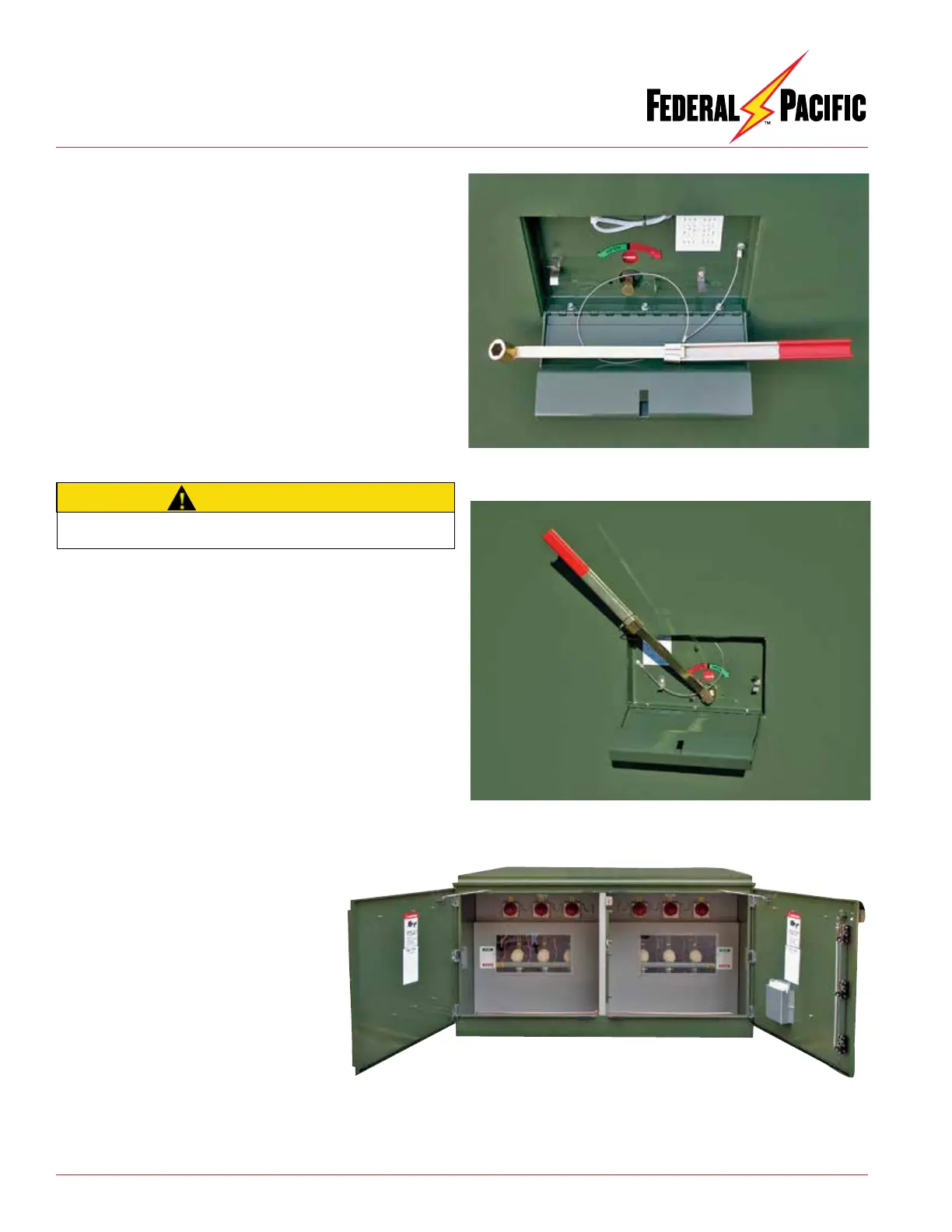
Figure 14. Remove and unfold handle. Secure handle in the extended
position by sliding clip over joint of handle sections.
Figure 15. Place operating handle on hex shaft of switch. Rotate handle
in desired direction as shown by switch position indicator.
2. Remove switch operating handle from storage clips. Unfold the
handle and secure in the extended position by sliding the clamp
over the hinged section (see Figure 14). Place the handle on the
hex switch-operating shaft (see Figure 15). If provision to padlock
switch in open or closed position is provided (K2 option), the
additional padlock (if installed) must be removed before access
to hex switch-operating shaft can be accomplished.
If key interlock(s) are provided (K1, K3 or K4 options), switch
may be locked in the open position.
3. Rotate handle in the direction as indicated on the label to open
or close switch. Verify switch position by observing the switch
position indicator in the handle pocket and by inspecting the
switch through the viewing window provided in each switch
compartment. (See Figure 16.)
4. Remove handle from hex shaft, fold it for storage and place in
the correct orientation on the clips for storage.
5. Close switch lockbox access cover and padlock.
Access cover should be padlocked whenever switchgear is
left unattended.
6. Switch position should be visually verified by opening access
door of switch compartment and checking actual switch posi-
tion through viewing window. See Figure 16.
CAUTION
Figure 16. Visually verify switch position through switch viewing window.