601 Old Airport Road • Bristol, VA 24201 Phone (276) 669-4084 • FAX (276) 669-1869 • www.federalpacific.com • ISO9001:2015
SECTION IB-2A-210
INSTALLATION & OPERATION INSTRUCTIONS
TYPE PSE PAD-MOUNTED SWITCHGEAR
NOVEMBER 2017, REV 4.2
PAGE 10
Figure 23. Shotgun-clamp stick secured to interlock lever.
9. Rotate the locking bracket to secure the fuse access plate
down against the lower door stile. The locking bracket is
located on the side of the fuse access plate. There is no
need to remove the shotgun clamp stick from the interlock
unit until the opening process is complete. See Figure 26.
10. Make certain that the fuse retainer bail, located at the pull-
ring end of the fuse assembly, has been pivoted off the end
fitting. See Figure
27.
11. Secure the hook of the shotgun clamp stick to the fuse pull
ring. Pull and lift the fuse assembly from the fuse mounting.
See Figures 25, 28 and 27. Alternately, if user’s standard
operating procedures permit, the fuse assembly may be
removed from the fuse mounting using an insulating-gloved
hand because in the lowered position the fuse mounting is
isolated at both ends from high voltage. See Figure 30. If
optional fuse storage hooks (suffix -E3 or -E4) are provided,
the complete fuse assembly can be stored on the hooks,
which are mounted on the fuse-compartment door. See
Figure 31.
12. Re-fuse using the procedures included with the fuse
manufacturer’s replacement fuse (or refill) unit.
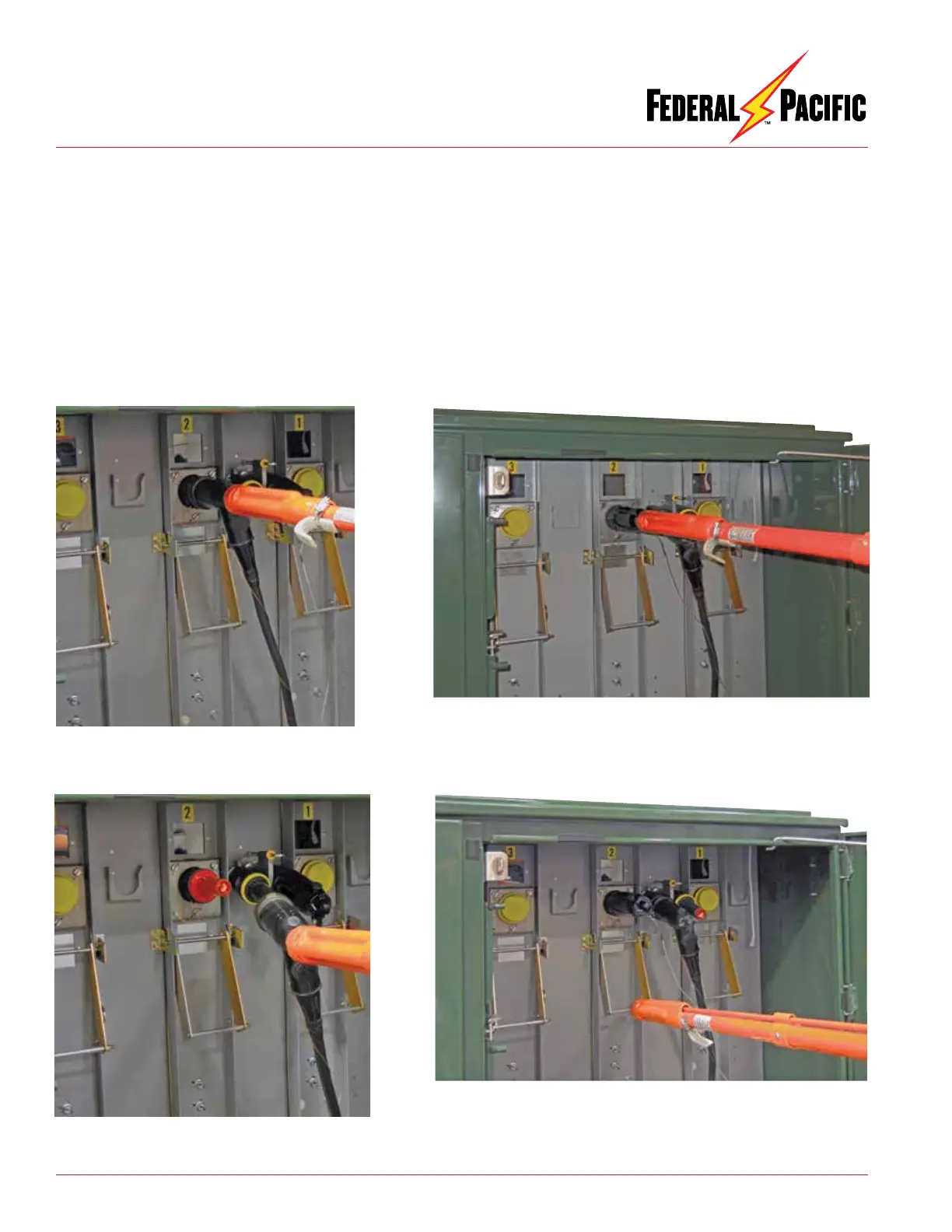
Figure 20. Shotgun clamp stick secured to elbow
with elbow in process of being removed/connected
to bushing insert.
Figure 21. Shotgun clamp stick secured to elbow
with elbow moved to feed through standoff bushing on
parking stand.
Figure 22. Insulating protective cover installed on bushing-well insert.
 Loading...