17
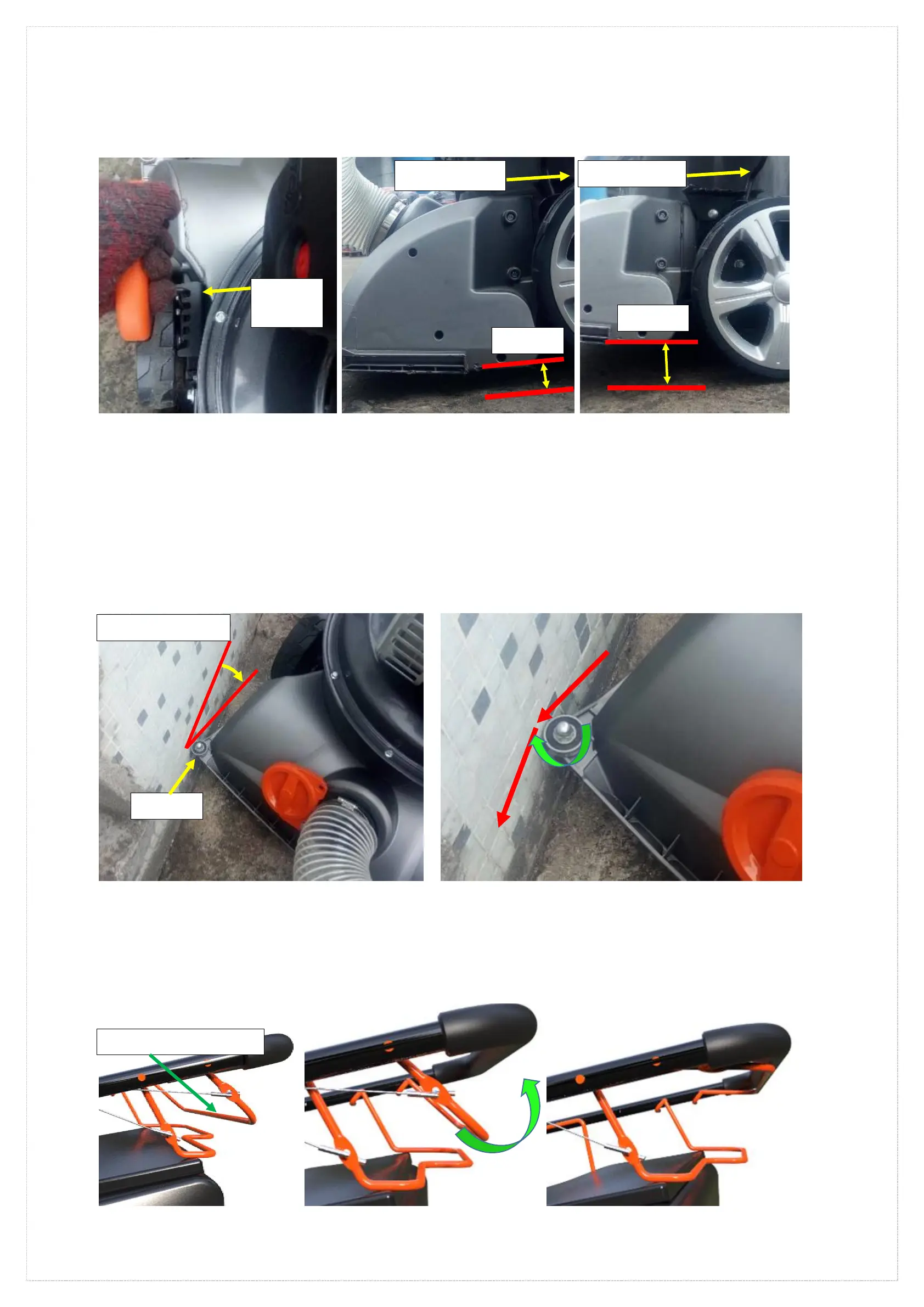
2) Adjust the height of the suction inlet
1. Pull the height adjustment handle out of the gear position slot and provide the height adjustment range according to the parameter
table of this manual (page 11) and select one gear position adjustment height from the 5 gear positions according to your use area or
situation. (See Fig 19-1, 2, 3)
Fig.19-1 Pull out the handle Fig.19-2 Height distance Fig.19-3 Height distance
3) △The use and function of the guide wheel
1. During normal speed (3.4 km/h) travel,Impact at an angle of less than 45 degrees When striking road steps、height exceeds (50mm-80mm)
and fixed hard objects,The guide wheel will rub against the hard object, causing the direction of travel to change. Thereby avoiding the hard
object and preventing the machine from being damaged by the violent impact of the hard object. (See Fig 20-1, 2)
●Note: Do not exceed the normal self-propelled speed (please provide self-propelled speed according to the parameter table of this manual
(page 11)) and impact at an angle greater than 45 degrees. Such operation will cause the guide wheel to lose its function and cause the suction
port to be damaged.
●Note: This function is an auxiliary function that protects the suction port for accidental impact. In normal times, please do not intentionally test
its strength. Please concentrate on operating the machine, slow down in advance and change direction to avoid hard objects.
Fig.20-1 Impact angle Fig.20-2 The role of the pulley
4) △Start and function of the roller brush
4)-1、Start roller brush
1. Please assemble the roller brush disc according to the procedure in 'Assembly Instructions', Assembly Step 5) roller brush Assembly (page 9).
2. After starting the machine, close the roller drive lever. (See Fig 21-1, 2, 3, 4))
Fig.21-1 Fig.21-2 Pull rod closing direction Fig.21-3 Clamping lever