VEK MNH Operating Manual v1.3 en
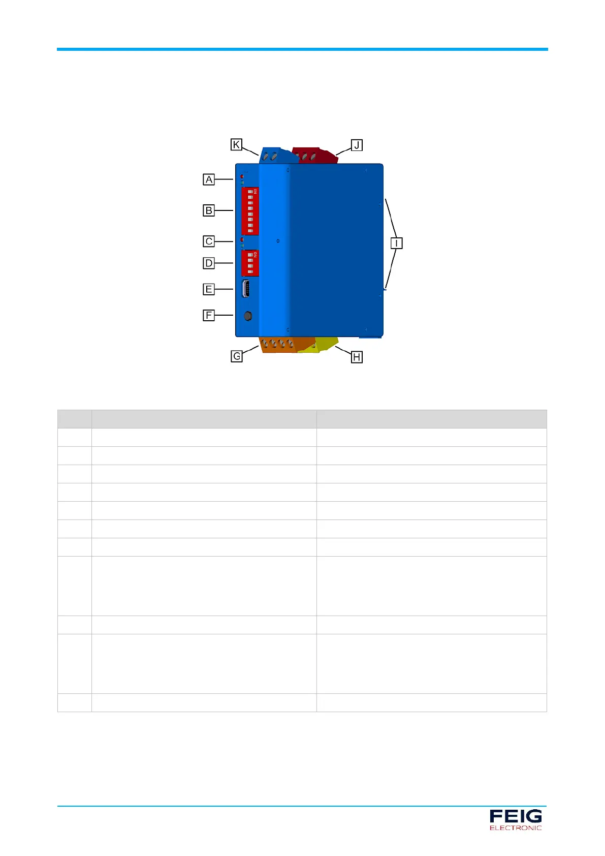
5.3 Device components
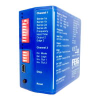
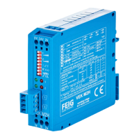
Fig. 3: Verkehrsdetektor VEK MNH
Loop channel LEDs 1 (red + blue)
Status indicators for the loops and the detector
Basic settings for the detector
Loop channel LEDs 2 (red + blue)
Status indicators for the loops and the detector
DIP switch 2 (MNH2 variant)
Basic settings for the detector
PC interface for configuration and diagnostics
Factory settings or fresh adjustment
Connections for induction loops
Output 1 terminal block:
• Relay output 1 (yellow, R24 variant)
• Open collector output 1 (green, O24
variant)
Signal outputs for controller
Mounting device for TS35 DIN rail
Output 2 terminal block:
• Relay output 2 (red, R24 variant)
• Open collector output 2 (green, O24
variant)
Signal outputs for controller
Connections for power supply
Tab. 5: VEK MNH Traffic Detector
 Loading...