Assembly and electrical installation
VEK MNH Operating Manual v1.3 en
8 Assembly and electrical installation
In the following section, assembly and electrical installation are described.
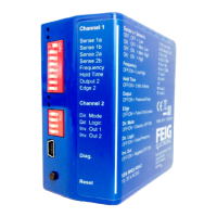
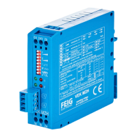
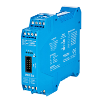
Illustrations and technical data on the device
You can find illustrations and technical data on the housing and connections in the sections at the
beginning of this document.
8.1 Assembly on the DIN rail TS35
Assembly conditions
Tools: none
Mounting device: DIN rail TS35
Fixing to the DIN rail
1. Place the device from above with the groove onto the top hat rail and lock the clip underneath.
2. Check that it is sitting securely.
The detector is ready for commissioning.
8.2 Connecting the power supply
Maintain the permitted voltage
The following power supplies are permitted:
• 10 - 30 VDC
• 10 - 26 VAC
Also refer to chapterDescription of connections .
Connect the inputs and outputs with no voltage present
All inputs and outputs must be connected before switching on the power supply.
• Insulated slotted screwdriver (width: 2 – 3 mm)
Connecting the power cable
1. Follow the warning and safety instructions and take the appropriate precautions.
2. If necessary, pull the terminal block out of the socket.
3. Loosen the screws on the blue terminal block.
4. Insert up to 5 mm of stripped cable into the slot at the side of the blue terminal block and fasten.
5. Tighten the screw.
6. If necessary, insert the terminal block back into the blue 2-pole socket.
The power cable is firmly attached to the terminal block with no exposed wires.
 Loading...