EN
8
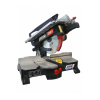
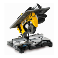
Legend Fig. 1
1 Control handgrip
2 Main switch start button
3 Base
4 Body/base swivel joint
5 Rotating bearing
6 Motor
7 Blade
8 Knob to unblock graduation
9 Button to unblock body descent
10 Permanent blade shield
11 Movable blade shield
12 Bar clamp shaft
13 Dust exhaust manifold
14 Piece holding clamp (optional)
15 Upper work surface
16 Movable upper safety guard
17 Bearing bracket
18 Support feet
19 Transport locking pin
20 Striker
1.10 TECHNICAL DATA
MODELS 280-280S
Tension and current .........................................230V – 5,5 A
Frequency (Hz) ................................................................ 50
Absorbed power (W) .................................................... 1300
No-load speed (r.p.m.) ................................................. 3000
MODEL 305S - 305W
Tension and current .........................................230V – 5,5 A
Frequency (Hz) ................................................................ 50
Absorbed power (W) .................................................... 1400
No-load speed (r.p.m.) ................................................. 3000
1.11 SWITCH (Fig. 2)
The switch is fi tted on the mitre saw prevents accidental
machine starting; however a locking position has also been
provided: see paragraph ELECTRIC CONNECTION.
Switch operating instructions
- Blocking device in OFF position: the switch is protected
against accidental start ups by a pushbutton that lock A
(blocking device in off position) and which will only allow
the machine to start up under specifi c conditions (Fig.
2A).
- Start up: to start up the machine press key 51 and keep
it pressed down while simultaneously moving the lever
of the switch 52 (Fig. 2B).
- Blocking device in ON position: the switch can be
locked in ”ON” position pressing key 51, move switch
lever 52 to the end of its travel (motor running) then still
holding lever 52, it is only necessary to release key 51
(Fig. 2C – 2D)
.
ATTENTION: To unlock the switch, press the button
51 and release the 52 switch lever.
1.6 SAFETY PROCEDURE FOR FURTHER RISKS
- Do not force the machine unnecessarily: excessive
cutting pressure may lead to rapid deterioration of the
blade and a decrease in performance in terms of fi nish
and cutting precision.
- When cutting aluminium and plastics always use the
appropriate clamps: all workpieces must be clamped
down fi rmly.
- Avoid accidental starts: do not press the start button while
inserting the plug into the socket.
- Always use the tools recommended in this manual to
obtain the best results from your cutting-off machine.
- Always keep hands away from the work area when the
machine is running; before performing tasks of any kind
release the main switch button located on the handgrip,
thus disconnecting the machine.
- Ensure the locking pin 19 (Fig.1) is inserted completely
when the machine is used as a circular saw.
1.7 NOISE CONDITIONS
- The frequency root mean RMS weighed for hand-arm
acceleration does not exceed 2.5m/s²;
- The level of weighed equivalent continuous acoustic
radiation pressure A is equivalent to 95 dB (A);
- The noise level is 102 dB (A).
NOTE: When cutting aluminium the use of
protective earphones or ear plugs is absolutely
necessary.
The use of this gear is also recommended for all
other uses.
1.8 INFORMATION ABOUT LECTROMAGNETIC
COMPATIBILITY
The European regulations on safety, and in particular
2014/30/EU, contemplate that all the equipment be equipped
with shielding devices against radio interferences both from
and towards the outside.
This machine is safe and in compliance with above
regulations.
Tests were carried out according to the EN 55014-1, EN
55014-2.
1.9 MACHINE DESCRIPTION (Fig. 1)
The mitre-saw machine consists of three basic parts: the
machine body complete with motor 6 which is integrated into
lower part 3 by means of the joint 4 and the swivel support 5,
and the upper work unit consisting of the work table 15, the
rest square 17 and the movable blade cover 16.
The base 3 is used as a support when cutting and butting
operations have to be carried out in the diff erent available
angles; the upper table is used as a support when trimming
or sectioning large planks of wood, and particularly when
cutting wood along the grain.
 Loading...