12
(1
$'-867,1*)LJ
:$51,1*$OO WKH DGMXVWPHQW SURFHGXUHV
LOOXVWUDWHG EHORZ PXVW EH SHUIRUPHG ZKHQ
WKHPDFKLQHVPRWRULVWXUQHGRII
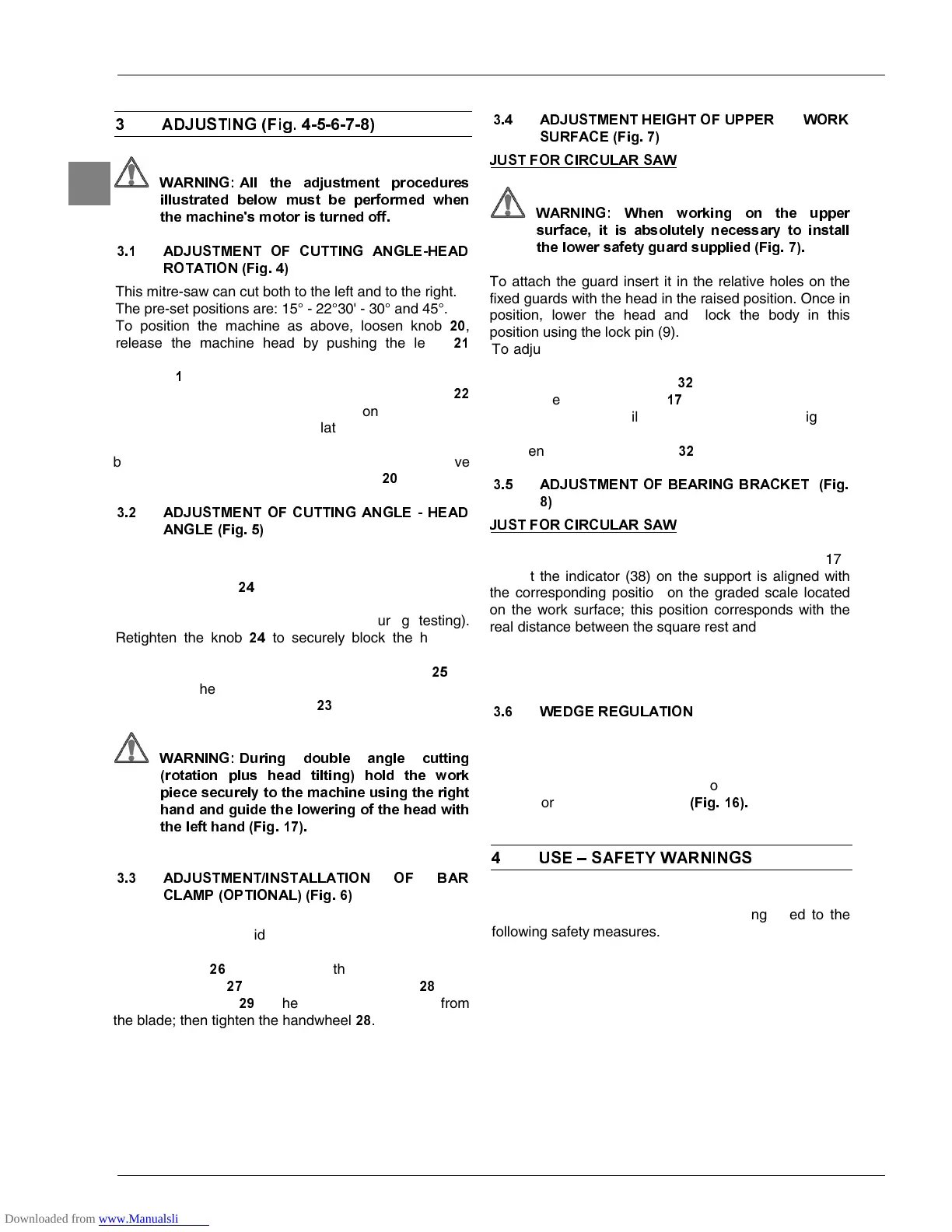
$'-8670(17 2) &877,1* $1*/(+($'
527$7,21)LJ
This mitre-saw can cut both to the left and to the right.
The pre-set positions are: 15° - 22°30' - 30° and 45°.
To position the machine as above, loosen knob
,
release the machine head by pushing the lever
downwards and rotate the rotary support by using the
handgrip
.
The head stops automatically each time the pointer
is aligned with the corresponding position etched on the
graduated scale of the rotating plate.
For all the intermediate positions, once the indicator has
been aligned with the position indicated on the relative
plate, block the swivel support using knob
.
$'-8670(172)&877,1*$1*/(+($'
$1*/()LJ
The machine head can be tilted to a maximum of 45° to
the left.
Release the knob
on the rear part of the machine
and tilt the head until it comes to rest on the stopper at
an angle of 45° (already calibrated during testing).
Retighten the knob
to securely block the head in
place.
For all other intermediate positions, align index
on
the rear of the head with the corresponding position
marked on the graduated scale
of the swivel joint.
:$51,1*'XULQJ GRXEOH DQJOH FXWWLQJ
URWDWLRQ SOXV KHDG WLOWLQJ KROG WKH ZRUN
SLHFHVHFXUHO\WRWKHPDFKLQHXVLQJWKHULJKW
KDQGDQGJXLGHWKHORZHULQJRIWKHKHDGZLWK
WKHOHIWKDQG)LJ
$'-8670(17,167$//$7,21 2) %$5
&/$03237,21$/)LJ
o cut work pieces of the same length, use the bar
lamp in order to avoid repeating the same measuring
procedure more than once.
crew the bar
into the hole in the base and block it
ith the dowel
: loosen the handwheel
and
position the clamp
at the appropriate distance from
he blade; then tighten the handwheel
.
$'-8670(17+(,*+72)
:KHQ ZRUNLQJ RQ WKH XSSHU
VXUIDFH LW LV DEVROXWHO\ QHFHVVDU\ WR LQVWDOO
WKHORZHUVDIHW\JXDUGVXSSOLHG)LJ
o attach the guard insert it in the relative holes on the
ixed guards with the head in the raised position. Once in
position, lower the head and block the body in this
position using the lock pin (9).
To adjust the height of the upper work surface to obtain
desired cutting widths, follow the instructions below:
loosen the two handwheels
;
move the bearing bracket
toward the blade;
until the desired cutting height is
tighten the two handwheels
;
$'-8670(172)%($5,1*%5$&.(7)LJ
Loosen the handwheel (37) and slide the square (17),
o that the indicator (38) on the support is aligned with
he corresponding position on the graded scale located
the work surface; this position corresponds with the
real distance between the square rest and the centre line
his position corresponds to the actual distance of the
bearing bracket rest from the centre line of the blade.
:('*(5(*8/$7,21
o ensure the dividing wedge is in the correct position,
keep it at a distance of between 3mm - 8mm from the
ooth of the blade. Should this not be the case, loosen
he screw which holds it attached to the arm and move it
o the aforementioned distance
)LJ
86(±6$)(7<:$51,1*6
After having performed all the above procedures and
operations, you may begin cutting, paying heed to the
following safety measures.
 Loading...