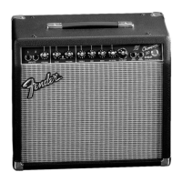
CHAMPION™ 30 DSP
(This is the model name for warranty claims)
4
SERVICE NOTES
1. CHASSIS REMOVAL is accomplished by first
removing four (4) screws from the top of the
cabinet; detach the speaker wires from the
speaker and then slide the chassis toward the
rear of the cabinet.
2. uDSP PCB ASSEMBLY REMOVAL is accom-
plished by disconnecting the ribbon cable on
the PCB Assembly, releasing the tabs on each
of the plastic stand-offs which the PCB assem-
bly is mounted. Removal of the uDSP PCB
assembly may be necessary should any of the
Digital Effects operate improperly.
3. CHAMPION 30 DSP MAIN PCB REMOVAL is
accomplished by removing the following items:
All Knobs and potentiometer bushings, four (4)
nuts and washers at the Input, Footswitch and
Headphone Jacks, two (2) screws at the Heat-
sink which attach to the Chassis, five (5) screws
at ST1 – ST5. Disconnect the Transfomer
Leads at P1, P3, P4, P5, and P11. Disconnect
the White and Black speaker wires at P13 and
P14. Disconnect the White and Black wires at
the Power Switch connected to WJ1 and P9.
Disconnect the Ribbon Cable at P2. Pull the
Red Tulip LED Assembly out of the jeweled pi-
lot light.
PCB EXCHANGE POLICY
Parts marked with a single asterisk (
*
) in the Part
Lists (starting on page 9 are not field replaceable. If
a failure due to one of these components is de-
tected, please contact the Fender® Dealer
Customer Service Department to order the com-
plete PCB Assembly.
 Loading...