Do you have a question about the Fender Deluxe 112 and is the answer not in the manual?
Defines standard codes for identifying capacitor types and values.
Defines standard codes for identifying resistor types and values.
Defines standard codes for identifying various hardware components.
Lists all components and their reference designations for the main PCB.
Details components and parts required for the amplifier chassis.
Lists parts and components specific to the amplifier cabinet.
Lists components for the footswitch unit and its associated cable.
Lists general miscellaneous parts not specific to major assemblies.
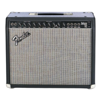
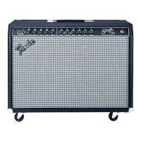
| Speaker | 12-inch Fender Special Design |
|---|---|
| Channels | 2 (Clean and Drive) |
| Reverb | Yes |
| Type | Solid State |
| Inputs | 2 x 1/4" |
| Outputs | 1 x 1/4" |
| Controls | Gain, Volume, Treble, Bass, Mid, Reverb, Drive Select |
| Footswitch | Yes (Channel Switching and Reverb On/Off) |