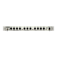
TBP-1
®
™
(This is the model name for warranty claims)
6
sented to rear panel switch S3 for selection of the
Balanced Line Output signal source. The level of
this XLR output (J9) is controlled by R176 in the
feedback loop of U10-B, whose output drives the
Jensen Line Output transformer T1. C86 prevents
any U10-B output DC offset from reaching T1 to as-
sure extremely low unwanted distortion (THD).
Diodes D28-29 clamp any excessive T1 kickback
voltage transients to +/- 16VDC in order to protect
U10-B’s output. Front panel Mute switch S5 (or the
Mute footswitch) controls FETs Q8 and Q9 to mute
all outputs except the Tuner and FX Send. Activat-
ing the Mute function also enables the low-
frequency oscillator (U18-B) to flash the front panel
Mute LED (D48).
POWER SUPPLY
The power supply employs a low-profile power
transformer having two secondary windings with a
common center-tap. This tap connects directly to
chassis ground through Faston tab P9 and the ad-
jacent PCB mounting screw and PEM standoff.
The Violet/Violet secondary winding is full-wave
rectified by diodes D56 and D57 and filtered by
C107-109 to provide a single-ended +265VDC plate
supply for the tube circuitry. The fused low-voltage
winding (RED/RED) is full-wave rectified by diodes
D58-61 and regulated by 3-terminal voltage regu-
lators U22-23 to provide +/-16VDC for the rest of
the circuitry.
Heater voltage (24VDC for two series-connected
12AX7s in the preamp) is derived from the 32VDC
(+/-16VDC) supply. Excess voltage is dropped
across paralleled ballast resistors R240-242.
FOOTSWITCH CIRCUITRY
Low-voltage AC is supplied for the remote four-
button footswitch at Footswitch Jack J10 via
current-limiting resistor R181. Inside the footswitch,
a combination of signal diodes, Zener diodes and
the function-indicating LEDs themselves act as
voltage references. Each phase (positive and
negative) of the AC waveform present on the tip
connection of J10 will be clipped to one of four
unique levels, depending on which footswitches are
open or closed. D31 allows comparators U17-A
and U17-B to sense and decode the negative
phase (smoothed out by C92), while D32 allows
comparators U19-A and U19-B to sense and
decode the positive phase (smoothed out by C93).
References for the comparators are derived from
Precision 10V Reference ICs U20-21 and their
associated 1% resistors R186-195. When the
footswitch is not connected or available, Zener
diode D30 (connected to the tip shunt of J10) sets
the comparator outputs appropriately for normal
front-panel switching of the Gain, Vari-Q
TM
and Mute
functions and for assuring that the FX loop is active.
.
 Loading...

