EX 200™ Internal Trouble Indicators
The EX 200™ fully supervises all of the components of the system, including itself, by
performing 22 tests every second. When a fault is detected, the control panel turns on
the FAULT indicator and the corresponding trouble indicator inside the panel,
de-energizes the appropriate trouble or warning relay depending on the fault, and
sounds the horn intermittently if the system is armed.
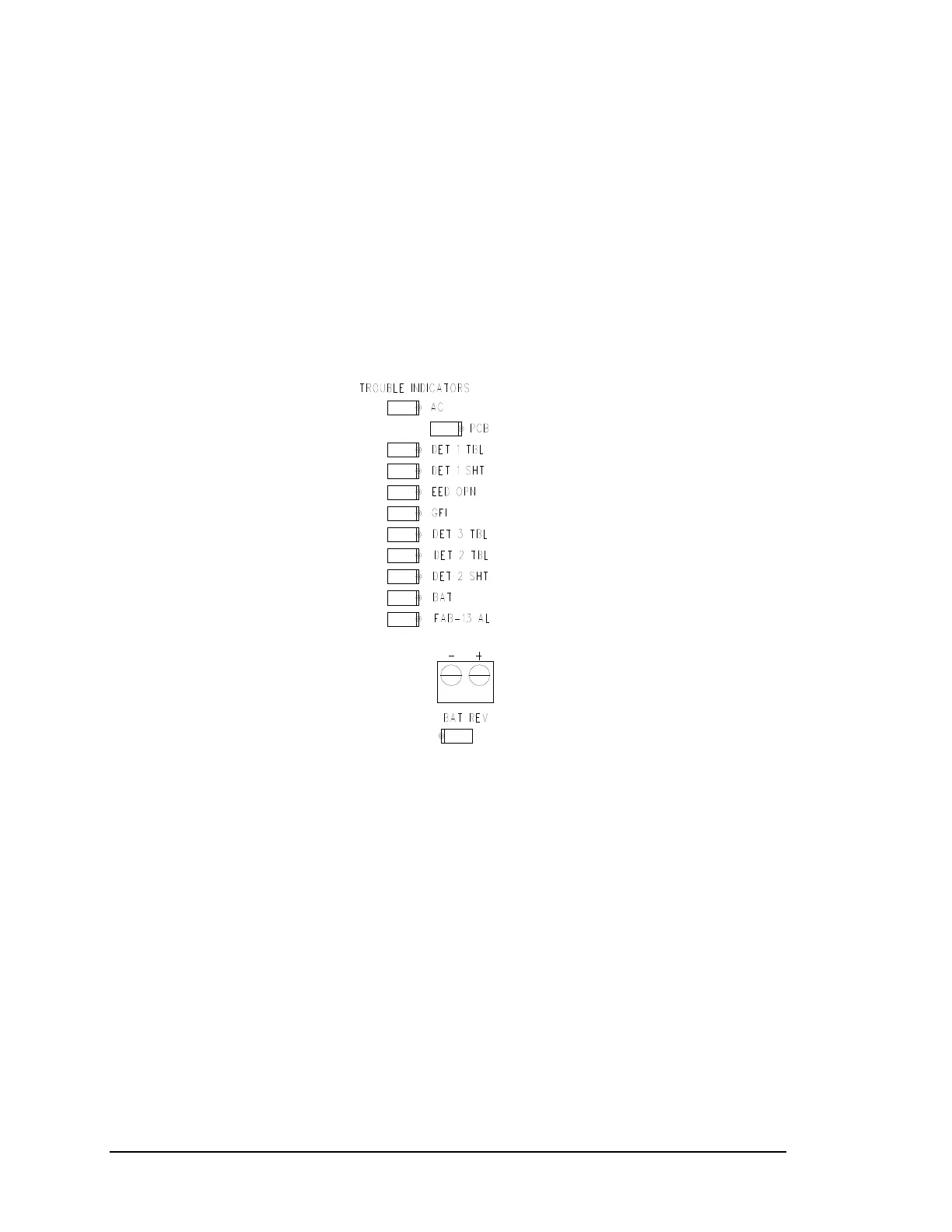
Twelve LED trouble indicators located on the PCB are visible when the front panel is
open. Eleven are grouped together above the battery connector; the twelfth is located
below the battery connector. Figure 2 notes the location of these indicators and Figure 3
illustrates the indicators in detail.
Figure 3: Detailed View
of Trouble Indicators
The indicators and the troubles that they report when lit are shown in Table 2. The
twelve PCB troubles that cause the PCB trouble indicator to light, and the associated
codes, are listed in Table 3. When the EX 200™ is disarmed, holding the HORN
SILENCE pushbutton pressed for at least five seconds will cause the control panel to
report all detected PCB trouble codes.
The trouble code is signaled by the PCB trouble indicator blinking a number of times
equal to the trouble code number (codes 1 to 12, listed in Table 3), with a five-second
pause between codes. If more than one trouble is present, the codes of all of the
troubles present will be blinked sequentially.
The blinking timing is ¾-second on and ¾-second off. The code or codes will be blinked
for one minute and then the EX 200™ will revert to normal operation.
Page 16 FSS/MC-519 Rev BC FENWAL
Protection Systems
 Loading...