BEFORE USING THE SAW
Ensure the saw is unplugged from mains before
making adjustments, mounting accesories or chan-
ging blades.
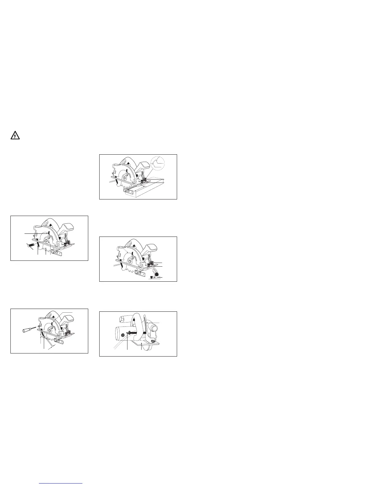
CHANGING/FITTING SAW BLADES
Refer to illustration below
- Depress the spindle lock lever (6) and keep it pressed,
then use the 13mm box spanner (2) provided to turn
the blade-retaining bolt anticlockwise.
- Remove the bolt, washer and blade if fitted. Make sure
the flange is present on the shaft and is the right way up.
- Open the blade guard with lever (1) and replace or fit
the saw blade with the teeth facing the same way as the
riving knife (4) - the teeth face towards the front of saw.
- Fit the washer and bolt (clockwise) hand tight.
- Depress the spindle lock lever and keeping it pressed,
tighten the bolt securely with the box spanner.
- Check that the blade guard is free to revolve and that
the blade does not touch any part of the casing or guard.
- After fitting a new blade it may be necessary to adjust
the riving knife.
ADJUSTING THE RIVING KNIFE
Refer to illustration below.
- Use a suitable screwdriver (not supplied) to loosen
both screws (2)
- Rotate Blade guard with lever (1) and keep open while
adjusting the riving knife. Refer to the illustration for
minimum and maximum distances.
- Tighten both screws securely.
- Check that the riving knife is in the correct position and
is in line with the blade.
- Release the blade guard.
MOUNTING THE PARALLEL GUIDE
Referring to the illustration below.
- Loosen thumbscrew (1)
- Slide the parallel guide (2) into slots with the fence
facing downwards.
- Set guide to the required position
- Tighten thumbscrew.
ADJUSTING THE CUTTING ANGLE
Referring to the illustration below.
- Loosen (anticlockwise) the thumbscrew (1) on the
angle quadrant and the locking lever (rotate anti-
clockwise) located at the rear of blade.
- Set the shoe to the desired angle 0-45 degrees.
- The cutting angle is indicated by the pointer (3)
- Securely tighten the thumbscrew and the locking lever.
ADJUSTING THE DEPTH OF CUT
Referring to the illustration below.
- Loosen locking lever (1) anticlockwise.
- Move the shoe (2) downwards to required depth
marked on quadrant (3)
- Securely tighten locking lever clockwise.