Pag. 49
Technical
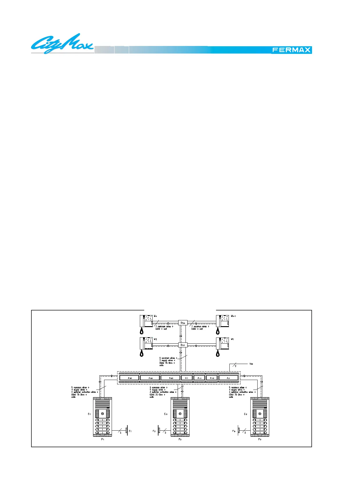
General diagram for a video door phone installation in buildings with three entrances.
BASIC FUNCTION
Pressing a button on the outdoor panel causes the call
signal Cp1, which is generated in the amplifier, to be sent
along the call line to the corresponding monitor, which pro-
duces the typical tremolo call tone. As it passes through
the excitation terminals (I-K) of the switcher, at the same
time it connects the corresponding outdoor panel.
Upon picking up the receiver, a switch connects the moni-
tor to the common audio wires (2 & 6), thus establishing
communication with the outdoor panel from which the call
was made.
Pressing the door release button on the monitor connects
wires 1 & 3 of the installation, making the amplifier activate
SCHEMATIC DIAGRAM
the door release of the panel from which the call was made.
OBSERVATIONS
Communication is limited to 90 seconds whichever the panel
originating the call. After this time, the call is ended.
This diagram shows an installation with three entrances.
For an installation with more entrances we advise the use
of Digital Systems (MDS).
To make things clear, the wiring diagram is divided in two
sections which are presented together: ENTRANCES and
FLOORS.
Two types of FLOOR diagram are shown: distribution in
2 or 4 dwellings per floor.
MATERIAL NEEDED
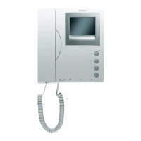
In the dwellings
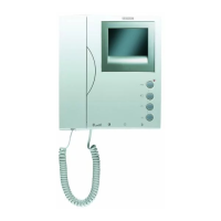
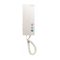
M1, M2, ...Mn CityMax Export Monitor Ref.: 8023 (do not forget the connector Ref. 8033)
D2.1, ..., D2.n Video Distributor Ref.: 2448 ó 2449 (depends on the distribution)
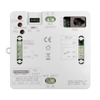
In the communal interior area
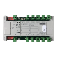
A1.1, A1.2 Audio Power Supply Ref.: 8787
A7 Distributor Power Supply Ref.: 88231
A3 Video Power Supply Ref.: 88302 (un alimentador cada 60 monitores)
A6.1, A6.2, A6.3 Vídeo Switcher Ref.: 8812
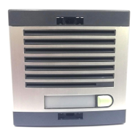
In the street
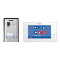
P1, P2, P2 Outdoor Panels (combination neccessary. Do not forget telecameras Ref. 8028).
F1, F2, F3 Electric lock Ref.: 2911 (for other types consult catalogue.)
E 2.4 VIDEO PHONE SYSTEM
BUILDING WITH THREE ENTRANCES